Forum sponsored by:

WARCO WM-250 lathe family and WM16 mill
Discussiona about the warco etc WM-250, 280 & 290 lathes and the WM series mills
| Mark P. | 20/06/2014 17:03:27 |
 634 forum posts 9 photos | Hi all, has anyone out there considered fitting an inverter drive to their WM16 mill? If you did or were to fit one would you keep the 2 speed gearbox? I understand that the gears are plastic but have never had a problem with them in 5 years of ownership,I also believe that metal replacement ones are available but where from.Any thoughts welcome. Regards Mark P. |
| Rik Shaw | 20/06/2014 17:55:59 |
 1494 forum posts 403 photos | Hello Mark - No, never considered fitting an inverter drive to mine but I seem to remember that someone on here claimed that steel gears were available through ArcEuro - I maybe wrong though (memory issues if you understand!). I also seem to remember that there was a caution when fitting steel gears as the plastic ones would strip before damaging other parts of the machine in the event of a "stackup". |
| Mark P. | 20/06/2014 20:32:44 |
634 forum posts 9 photos | Hi Rik, I have seen some similar looking gears on the Arc Euro web site but not sure that they will fit. I don't want to strip the mill only to find that I need to make parts to fit the new motor and drive train. The idea of the inverter drive is I seem to use a lot of brushes (3 sets in 5 years) they seem to be on the way out now. Regards Mark P. |
| Ian S C | 21/06/2014 13:13:17 |
 7468 forum posts 230 photos | Arc Euro seem to have 2 replacement metal gears in the catalogue, they are for the mini lathes, one is 21/29T for the high low gear on the spindle, the other is 12/20T for the high low on the gear shaft, you better check, but I'm sure someone said they suited the gear head Sieg mill. The brushless motors sound like a good idea, although I'll stick to an AC induction motor, and my belt head with back gear, and keep away from the electronics(I think the electronic speed control is just a way of building a cheap machine, not a durable one). Ian S C |
| Tim Stevens | 21/06/2014 15:27:04 |
 1779 forum posts 1 photos | Posted by Ian S C on 21/06/2014 13:13:17:
Arc Euro seem to have 2 replacement metal gears in the catalogue, they are for the mini lathes, one is 21/29T for the high low gear on the spindle, the other is 12/20T for the high low on the gear shaft, ... If it helps, the gears in the Chamion 20V mill (bigger brother from Chester) are: Motor to spindle1 - 25 : 46 Spindle1 to spindle2 - low 42 : 80, high - 62 : 60 Cheers, Tim |
| Mark P. | 21/06/2014 17:21:18 |
634 forum posts 9 photos | Does anyone know if both sets standard gears are plastic, or just one? Regards Mark P. |
| Neil Wyatt | 21/06/2014 21:12:10 |
 19226 forum posts 749 photos 86 articles | I replaced the gears with a poly-v belt on my X2. I may consider adding a second set of pulleys to give a higher speed, but probably won't. They are vastly quieter than the gears. Neil |
| john kennedy 1 | 22/06/2014 06:45:14 |
 214 forum posts 24 photos | I've got a vfd on my Harrison mill and one on my WM250. I found the low speed torque is not as good as they like to make out and its handy to to slip the gear or belt down when doing heavy cuts at slow speed. |
| Ian S C | 22/06/2014 10:27:19 |
7468 forum posts 230 photos | Both the sets of gears from Arc Euro are metal, presumably steel. Ian S C |
| Russell Eberhardt | 22/06/2014 11:06:02 |
 2785 forum posts 87 photos | I found that the biggest benefit of fitting an inverter drive to my little mill (Warco ZX-15) was the better finish as a result of lower vibration. Go for it. Russell. |
| Mark P. | 27/06/2014 14:32:19 |
634 forum posts 9 photos | Thanks for the replies chaps,looks like the project may be a goer! Just had a minor windfall so can get 90% of what's needed to start. Have found an inverter/motor package for just under £200. My idea of retaining the 2 speed gearbox was so I would have a sort of backgear albeit minor I feel that it would be a bit of an advantage. I plan to run the primary drive with a toothed belt to the original input shaft of the gearbox. Regards Mark P. |
| mechman48 | 11/07/2014 18:08:38 |
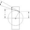
 2947 forum posts 468 photos | For us that have this type of lathe I thought I would update you with an alignment check I did on Tuesday, did post it originally in thread 'What I did today'... I did a tailstock alignment check & test after a years use, used a coaxial centering indicator which showed a run out of 4 divisions with the quill extended approx’ 30mm & locked plus the shortest leg on the indicator. The tailstock was adjusted to within 1 ½ division on the indicator & adjusters locked. I left it within that range as the initial check started out with a run out check at the chuck with a 16mm chromed shaft from a printer protruding 15mm & set at zero, swung 180* which indicated a run out of 1 ½ thou’. Did a couple of test cuts with set up as shown in pics, only had to tweak tail stock again twice & manage to achieve final figures as shown, so if my maths is still compos mentis I have a difference of .00045” … which is less than ½ thou’ … .001mm, over a 6” /150mm, length… I think I can call that ‘aligned’ for my intents & purposes. The measurements were taken with a Mitutoyo 0 – 1” digi mic which is capable of reading to .00005” / .001mm, as can be seen in pic 5.
.0015" thou run out at chuck...
Machining set up...
Tailstock reading...
Headstock reading...
Differential over 6" - .000045"... less than half a thou', pretty good adjustment I reckon, (or just b***y lucky! Not intending the 'granny & eggs' cliché but it's worth checking alignment a couple of times over the year just to give yourself some idea what your machine is doing. George. |
| mechman48 | 30/07/2014 17:19:53 |
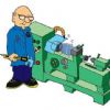
2947 forum posts 468 photos | Assistance needed from electrikery guys; I have just completed fitting a power feed to my WM16 X axis using a 110/220v – 12v transformer & a PWM motor speed controller, both from China (e bay) & a 12v windscreen wiper motor, all seems well, except that after a trial run cutting a aluminium block with cuts up between .50 - 1.00mm, a 19 mill & 50mm indexible tip facing cutters alternately, the motor is starting to get warm, not hot but increasing in temperature over a period of time. The slowest feed rate I can get is 18mm per min & the fastest is 140mm per min (linear), I haven’t checked the rpm of the motor (I reckon on 30-40rpm at a rough observation) & I haven’t got a clamp amp to see what amps the motor is drawing although I believe you can use a multi-meter to check amps. I can understand that the torque to turn the motor against the drag of the wiper blades can be reasonable, so I am assuming that the torque required to turn the leadscrew is much greater, but not so much that would cause the motor to get overly warm, what am I missing out on, as others who have fitted this type of drive don’t seem to mention anything about the motor getting warm? wouldn't like to be using for any long period of time as not overly keen on watching that magic smoke appear! Link to e bay for the PWM controller… Have att. some pics of setup …
Modified motor drive...
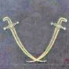
Am now looking at modifying the drive connection to make it easier to apply a quick disconnect I have some thoughts on this although I have seen a few on you tube that apply some form of forked device but other ideas would be welcome? Cheers George.
Edited By mechman48 on 30/07/2014 17:38:56 Edited By mechman48 on 30/07/2014 17:46:44 |
| mechman48 | 30/07/2014 17:45:42 |
2947 forum posts 468 photos | Cover fitted, with expanded metal for safety aspect..
Cheers George. ps.. for the eagle eyed purists; the brackets on the table are for additional support when I wind the head up & down as it does vibrate somewhat but there is no vibration when machine in use, & the grinder on the left does get moved out of the way when I need to use it, it's convenient to store it there at the mo', I plan to extend the footprint of the table later when I can get round to fabricate a frame & get it welded up... Edited By mechman48 on 30/07/2014 17:57:43 |
| mechman48 | 01/08/2014 14:45:18 |
2947 forum posts 468 photos | A video of trial run...
George. ps. can't remember how to load up videos other than this method.. could someone remind me please...? Edited By mechman48 on 01/08/2014 14:55:52 I don't think there is an easy way to do it with a viodeo from Photobucket so I've just added a simple link. J Edited By JasonB on 01/08/2014 16:04:40 |
| MM57 | 01/08/2014 16:25:26 |
| 110 forum posts 3 photos | Nice one George - well done As an aside, what DRO scales are you using (make/model/optical/magnetic) and what do you think of them? ...and what did you settle on for the "quick disconnect" (my parts are on the way from the 'bay also) Edited By Martin Millener on 01/08/2014 16:29:03 |
| Ed Duffner | 01/08/2014 17:06:27 |
| 863 forum posts 104 photos | Hi George, Good job! I'd like to do something very similar on my WM16 and try to include some kind of relay or contactor drop out for when the motor stops unexpectedly. I don't think it's an issue for the motor to become warm under use although hot might be a concern, depends where we draw the warm/hot line. I'm curious to understand how a two wire motor can be operated by a PWM control. I thought the motor had to have some sort of additional wiring to send EMF back to the electronics. Does having a power feed also reduce back pain. I seem to get quite a lot of pain after a couple of hours of winding by hand setting up and winding again etc. I'm 6' 1" Cheers,
|
| Rik Shaw | 01/08/2014 17:32:42 |
1494 forum posts 403 photos | Looks impressive George - a nice job! Let us know how it stands up under a torquey load - particularly at the slower speed. I'd like to have power drive myself but sadly no room in my miniscule workspace. Even without a WARCO power drive on the X (which would have been my chosen method) with the table wound over to the left to its fullest extent I am unable to get out of the shed door unless I crouch down and crawl under the table. It doesn't get much more cramped than that! Rik (6 foot tall and finding it increackingly hard - and sometimes unwilling - to bend, kneel or grovel, especially grovel ! ) |
| Neil Wyatt | 01/08/2014 17:47:59 |
19226 forum posts 749 photos 86 articles | > My idea of retaining the 2 speed gearbox was so I would have a sort of backgear The ratio is roughly 2:1. For my lathe I decided it was better to drive the spindle direct and have a stepped pulley on the motor. The gears are still ion their, but redundant. With the mill, I haven't had any issues using the motor and just one ratio, so far. Neil |
| mechman48 | 02/08/2014 13:00:02 |
2947 forum posts 468 photos | Thanks for the comments guys. JasonB... Thanks for the link, how did you do it? Martin... Used magnetic readouts bought from Arco Euro.. look in their index 'Measurement' for 'Digital readout bars with dedicated remote display' so far they work just fine, auto switch off so no chance of running batteries down, have had the batteries in for over a year now, look in my album for a couple of pics of how I fitted mine... as for the quick disconnect, I haven't come up with anything just yet, still mulling over it... Ed... Can't explain how the PWM speed controller works, not that into electrickery, Just know that I connected the positive & negative wires to the two motor wires, tested for right direction (switch wires over if not) & it runs fine. if you click on the link in my write up above you will see the PWM & its description. Re. the back problem, know what you mean, same here, (have start of arthritis in spine so that doesn't help) & my a**e is nearer to the floor than yours (5' 7" Cheers George |


 ...methinks I can safely call that 'aligned'
.jpg")
.jpg")
.jpg")
.jpg")
.jpg")
.jpg")
.jpg")

Please login to post a reply.
Magazine Locator
Want the latest issue of Model Engineer or Model Engineers' Workshop? Use our magazine locator links to find your nearest stockist!
Sign up to our Newsletter
Sign up to our newsletter and get a free digital issue.
You can unsubscribe at anytime. View our privacy policy at www.mortons.co.uk/privacy
Latest Forum Posts
- *Oct 2023: FORUM MIGRATION TIMELINE*
05/10/2023 07:57:11 - Making ER11 collet chuck
05/10/2023 07:56:24 - What did you do today? 2023
05/10/2023 07:25:01 - Orrery
05/10/2023 06:00:41 - Wera hand-tools
05/10/2023 05:47:07 - New member
05/10/2023 04:40:11 - Problems with external pot on at1 vfd
05/10/2023 00:06:32 - Drain plug
04/10/2023 23:36:17 - digi phase converter for 10 machines.....
04/10/2023 23:13:48 - Winter Storage Of Locomotives
04/10/2023 21:02:11 - More Latest Posts...
- View All Topics
Support Our Partners


Shopping Partners
Subscription Offer

Latest "For Sale" Ads
- Reeves** - Rebuilt Royal Scot by Martin Evans
by John Broughton
£300.00 - BRITANNIA 5" GAUGE James Perrier
by Jon Seabright 1
£2,500.00 - Drill Grinder - for restoration
by Nigel Graham 2
£0.00 - WARCO WM18 MILLING MACHINE
by Alex Chudley
£1,200.00 - MYFORD SUPER 7 LATHE
by Alex Chudley
£2,000.00 - More "For Sale" Ads...
Latest "Wanted" Ads
- D1-3 backplate
by Michael Horley
Price Not Specified - fixed steady for a Colchester bantam mark1 800
by George Jervis
Price Not Specified - lbsc pansy
by JACK SIDEBOTHAM
Price Not Specified - Pratt Burnerd multifit chuck key.
by Tim Riome
Price Not Specified - BANDSAW BLADE WELDER
by HUGH
Price Not Specified - More "Wanted" Ads...
Get In Touch!
Do you want to contact the Model Engineer and Model Engineers' Workshop team?
You can contact us by phone, mail or email about the magazines including becoming a contributor, submitting reader's letters or making queries about articles. You can also get in touch about this website, advertising or other general issues.
Click THIS LINK for full contact details.
For subscription issues please see THIS LINK.
Digital Back Issues


Donate

 Register
 Log-in
Model Engineer Magazine
- Percival Marshall
- M.E. History
- LittleLEC
- M.E. Clock

ME Workshop
- An Adcock
- & Shipley
- Horizontal
- Mill

Subscribe Now
- Great savings
- Delivered to your door

Pre-order your copy!
- Delivered to your doorstep!
- Free UK delivery!
All Forum Topics > Workshop Tools and Tooling > WARCO WM-250 lathe family and WM16 mill