Forum sponsored by:

WARCO WM-250 lathe family and WM16 mill
Discussiona about the warco etc WM-250, 280 & 290 lathes and the WM series mills
| Sam Longley 1 | 23/05/2016 13:25:48 |
| 965 forum posts 34 photos | Today I had a bit of a calamity & may have damaged my WM 250 lathe I was using the powered drive to reduce some bar stock & had the topslide retracted so that the tool was over the centre of the unit to maintain max rigidity of the tool. As the tool approached the chuck I did not notice that the carriage hit the stop & jammed the leadscrew. I made the mistake of trying to disengage the drive rather than turning off the power so it was forced up hard before the motor stalled This happened partly because my old Drummond M automatically disengaged at a set point & I was not used to having to make a special act to stop this Is there a switch that can be fixed onto the bed to disengage the power or has anyone actually fitted such a thing or is there any alternative to avoid a repeat of such stupidity |
| John Rudd | 23/05/2016 13:40:45 |
| 1479 forum posts 1 photos | It should be relatively easy to incorporate a micro switch to prevent such events. How electrical savvy are you? Is your machine the dc motor or 3 ph motor version? If yours has the dc motor, then there are a pair of connectors marked I1 and I2 on the pcb near the front. The switch can be wired to these terminals. If its the other version, you would need to wire into the fwd/rev sw.... Edited By John Rudd on 23/05/2016 13:53:27 |
| Sam Longley 1 | 23/05/2016 15:30:12 |
| 965 forum posts 34 photos | Posted by John Rudd on 23/05/2016 13:40:45:
It should be relatively easy to incorporate a micro switch to prevent such events. How electrical savvy are you? Is your machine the dc motor or 3 ph motor version? If yours has the dc motor, then there are a pair of connectors marked I1 and I2 on the pcb near the front. The switch can be wired to these terminals. If its the other version, you would need to wire into the fwd/rev sw.... Edited By John Rudd on 23/05/2016 13:53:27 Well I know it makes your hair stand on end when you poke your fingers in the plug holes I did not know that there were 2 types of motor , I assume I have 240 V as i plug it into a 13 amp plug socket Can you give some indication of where i find the PCB please
|
| John Rudd | 23/05/2016 15:56:10 |
| 1479 forum posts 1 photos | Sam, I dont know the WM series, my own lathe is from SPG and is probably the bigger brother, it does look similar. Mine came with a 1.5kw dc motor, so if yours is the similar dc motor driven smaller version, then the pcb is located in the box attached to the rear of the headstock.( as if stood in front of the m/c). I think its mounted on the right side as you look into the box.... Can you post pictures? |
| Sam Longley 1 | 23/05/2016 19:06:38 |
| 965 forum posts 34 photos | I think it is different. It is a 1.1 Kw delta Inverter drive Ac induction motor.- Whatever that is !!! I removed the chuck guard almost immediately & that has a mounting bar with a switch somewhere along the line that disables power when the guard is raised.. If that has 2 wires to it then I could divert them to another switch on the bed. That would mean i would not have to touch any PCB etc. I just need someone who has had one of these apart to give me the heads up on how best to go about it & if it is possible |
| Gray62 | 23/05/2016 19:53:00 |
| 1058 forum posts 16 photos | Hi Sam, I've got the same machine, Your machine has a 3 phase AC motor driven by the Delta inverter not a DC motor/pcb setup. You could re-use the chuck guard interlock connections, if memory serves me correctly, these can be accessed by removing the rear cover of the headstock, this is where the inverter is housed. Whilst you have access to the inverter there are some parameters that can be changed which improve the machine, I found that the speed ramp up and ramp down times were set to long, and also the DC braking settings were sub-optimal. If you are going to rely on a interlock switch to stop the lathe before it crashes, you will need the spindle to stop a bit quicker than it currently does. If you want more detail, send me a PM and I will provide more detail. I'll be back home at the end of the week, happy to give you a call if you include your number in the PM. Where in the country are you? |
| Sam Longley 1 | 23/05/2016 20:38:36 |
| 965 forum posts 34 photos | Thanks --Essex, CM0 7LY But I am off sailing to Channel Islands & then to Brest for the next couple of months starting in next couple of days However, if i could find which wires to use I am sure i could work out how to rig a switch. I could just extend them. Then I need to find a suitable switch. I am assuming 240 V. Is that correct ? |
| Gray62 | 23/05/2016 20:53:51 |
| 1058 forum posts 16 photos | Hi Sam, All of the interlock circuit is low voltage, 24v dc IIRC. Any medium/heavy duty microswitch with NC contacts should do the job fine. Enjoy the sailing and if you need any assistance with the lathe when you return please feel free to get in touch. Graeme |
| Sam Longley 1 | 23/05/2016 21:02:13 |
| 965 forum posts 34 photos | Graeme Thanks for that I will PM you on my return when I have confidently opened up the headstock & found I am lost !!!!!!!! |
| Enough! | 24/05/2016 01:03:47 |
| 1719 forum posts 1 photos | Posted by Sam Longley 1 on 23/05/2016 19:06:38: If that has 2 wires to it then I could divert them to another switch on the bed.
Not sure how you mean "divert them", Sam. If you mean taking removing them from the switch on the guard and using them instead for the carriage switch (thereby losing the safety switch on the guard) it ought to be possible to have both by wiring the second switch in series or parallel (depending how the guard switch operates). That way you'd have both safety switches operational. (Apologies if this is what you meant in the first place). |
| Sam Longley 1 | 24/05/2016 07:44:17 |
| 965 forum posts 34 photos | Posted by Bandersnatch on 24/05/2016 01:03:47:
Posted by Sam Longley 1 on 23/05/2016 19:06:38: If that has 2 wires to it then I could divert them to another switch on the bed.
Not sure how you mean "divert them", Sam. If you mean taking removing them from the switch on the guard and using them instead for the carriage switch (thereby losing the safety switch on the guard) it ought to be possible to have both by wiring the second switch in series or parallel (depending how the guard switch operates). That way you'd have both safety switches operational. (Apologies if this is what you meant in the first place). What I have done is removed the guard & rotated the bar so the machine thinks the guard is in place. I was considering just disconnecting the wires from the switch on the bar & re routing them to a new switch on the bed Now Graeme has told me it is 24 V I assume I need a limit switch from someone like RS Components I just need to sort out which one because Graeme has pointed out that the motor does not cut out instantaneously so I am not sure if that affects bed travel after it hits the switch so the switch may need to be a type of plunger or snap action & I have to determine which one Edited By Sam Longley 1 on 24/05/2016 07:51:45 |
| Ian Westlake | 18/03/2017 23:28:22 |
| 6 forum posts | Hello I'm after a favour - Please would someone provide the following measurements:
I want to work out what height a bench will need to be for the lathe I plan to buy (I will be welding a bench, however need to know the dimensions so that I can cut the metal). Thanks Ian Edited By Ian Westlake on 18/03/2017 23:28:58 |
| john kennedy 1 | 19/03/2017 08:27:28 |
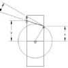 214 forum posts 24 photos | Hi Ian, Tray to spindle centre .. 309mm Tray to flat of bed .. 182mm Tray to saddle handle at 6pm ..80mm A little tip, make it high to prevent backache. John |
| SteveW | 19/03/2017 17:03:44 |
 140 forum posts 11 photos | I made my bench 895mm O/A. to the top which is made from one layer 18mm ply and kitchen worktop to finish. I am 5' 10"" and the handle on the cross slide is about on a level with my elbow. I thought 'too high and I can stand on a box; too low and I'll need to dig a hole...'. Has worked out just right for me. No back problems. |
| Ian Westlake | 19/03/2017 18:07:54 |
| 6 forum posts | Thank you to both of you, that's what I was after as I don't want to make it too low. I'm 5' 8", so I reckon 900mm height is about right, and if it isn't, I can knock up a duck board to stand on. |
| Martin Botting 2 | 19/03/2017 18:39:32 |
 93 forum posts 20 photos | Posted by Ian Westlake on 19/03/2017 18:07:54:
Thank you to both of you, that's what I was after as I don't want to make it too low. I'm 5' 8", so I reckon 900mm height is about right, and if it isn't, I can knock up a duck board to stand on. I built mine a tad to high but have now screwed 6" blocks of soft wood to my boots and its fine, apart from smashing my nut on the ceiling. |
| john kennedy 1 | 20/03/2017 08:38:05 |
214 forum posts 24 photos | You're about right there Ian. I'm also 5'8" and I made my stand 830mm from the floor so you can make your duck board to suit. John |
| Bob Rodgerson | 20/03/2017 19:21:35 |
| 612 forum posts 174 photos | I used to get backache when I was working on my BH 600 because it was bit low for me. When I bought my CNC mill I put both my BH600 manual mill (Superlux) onto moveable trolleys with lockable wheels, they were made from 4" channel and the castors were a further 4 inches tall so I increased their height considerably. As a result I no longer get backache when working at the lathe or the mill but I do get a lot more hot chips down my shirt from the lathe than ever before and I find it difficult to look over the top of the tool post. |
| mechman48 | 06/05/2018 14:56:28 |
 2947 forum posts 468 photos | Going back to this general thread of the Warco Family; have looked through this & done a search on 'oilers' & not having any results, could any one with a WM250V who has changed their oilers please let me know what size the ball oilers are on the saddle/ tailstock etc. A couple of mine need changing & rather than have to send back the wrong size or dig one out at the mo', I'd prefer if any member has the size to hand, or ref. link. IIRC somebody did mention the size 3/16 - 5mm, 1/4" - 6mm ?
|
Please login to post a reply.
Magazine Locator
Want the latest issue of Model Engineer or Model Engineers' Workshop? Use our magazine locator links to find your nearest stockist!
Sign up to our Newsletter
Sign up to our newsletter and get a free digital issue.
You can unsubscribe at anytime. View our privacy policy at www.mortons.co.uk/privacy
Latest Forum Posts
- *Oct 2023: FORUM MIGRATION TIMELINE*
05/10/2023 07:57:11 - Making ER11 collet chuck
05/10/2023 07:56:24 - What did you do today? 2023
05/10/2023 07:25:01 - Orrery
05/10/2023 06:00:41 - Wera hand-tools
05/10/2023 05:47:07 - New member
05/10/2023 04:40:11 - Problems with external pot on at1 vfd
05/10/2023 00:06:32 - Drain plug
04/10/2023 23:36:17 - digi phase converter for 10 machines.....
04/10/2023 23:13:48 - Winter Storage Of Locomotives
04/10/2023 21:02:11 - More Latest Posts...
- View All Topics
Support Our Partners


Shopping Partners
Subscription Offer

Latest "For Sale" Ads
- Reeves** - Rebuilt Royal Scot by Martin Evans
by John Broughton
£300.00 - BRITANNIA 5" GAUGE James Perrier
by Jon Seabright 1
£2,500.00 - Drill Grinder - for restoration
by Nigel Graham 2
£0.00 - WARCO WM18 MILLING MACHINE
by Alex Chudley
£1,200.00 - MYFORD SUPER 7 LATHE
by Alex Chudley
£2,000.00 - More "For Sale" Ads...
Latest "Wanted" Ads
- D1-3 backplate
by Michael Horley
Price Not Specified - fixed steady for a Colchester bantam mark1 800
by George Jervis
Price Not Specified - lbsc pansy
by JACK SIDEBOTHAM
Price Not Specified - Pratt Burnerd multifit chuck key.
by Tim Riome
Price Not Specified - BANDSAW BLADE WELDER
by HUGH
Price Not Specified - More "Wanted" Ads...
Get In Touch!
Do you want to contact the Model Engineer and Model Engineers' Workshop team?
You can contact us by phone, mail or email about the magazines including becoming a contributor, submitting reader's letters or making queries about articles. You can also get in touch about this website, advertising or other general issues.
Click THIS LINK for full contact details.
For subscription issues please see THIS LINK.
Digital Back Issues


Donate

 Register
 Log-in
Model Engineer Magazine
- Percival Marshall
- M.E. History
- LittleLEC
- M.E. Clock

ME Workshop
- An Adcock
- & Shipley
- Horizontal
- Mill

Subscribe Now
- Great savings
- Delivered to your door

Pre-order your copy!
- Delivered to your doorstep!
- Free UK delivery!
All Forum Topics > Workshop Tools and Tooling > WARCO WM-250 lathe family and WM16 mill