Forum sponsored by:

Rotary Laser centre finder
An unusual design centre finder for the mill
| John McNamara | 25/01/2014 04:29:31 |
 1377 forum posts 133 photos | Hi All I have so far not been inspired to build a Laser centre finder for the mill because of the difficulty of reading the fuzzy spot and the difficulty of keeping it truly on the axis of rotation of the machine when removing it and replacing it. The design shown in the video below overcomes these difficulties by angling the beam through the axis of rotation and rotating the spindle when taking a reading. Thanks the human eye's persistence of vision this forms a cone of light that shows up on the surface of the work as a ring. It also uses the eyes ability to centre objects between two points, By raising the quill you can make the lasers fuzzy edge just touch the points being compared your eyes make excellent comparators in this situation. The video shows various ways of using the tool. I particularly like the way it shows on a circular object as a ring that is angled unless the axis is truly perpendicular to the object. Looks like I will have to build one of these........ Link below (the device shows at 2 minutes 10 seconds from the start) I have not seen videos from this man ,Dan Gelbart before.. They would be a good start for beginners to learn about workshop processes. I have not seen them all maybe there are other gems like this one inside. Regards
|
| Thor 🇳🇴 | 25/01/2014 05:03:39 |
 1766 forum posts 46 photos | Interesting concept John, thanks for the link. Thor |
| Andrew Moyes 1 | 25/01/2014 06:07:50 |
| 158 forum posts 22 photos | Fascinating. Just what I need for centring holes etc. Strange it isn't commercially available yet. I've got to make one... Further on, he makes the case for a 4 jaw SC chuck which is my preference too for normal round and square stock. I'd always thought the 3 jaw was really for hex stock but I hadn't realised you could hold hex in a 4 jaw as well. The angled hole in the nut is a great idea too. Thanks for the link from me as well. I must watch some more of his videos. Andrew M |
| Michael Gilligan | 25/01/2014 08:46:21 |
 23121 forum posts 1360 photos | That's very neat, John ... thanks for the link. Incidentally, it is possible to improve the spot from a LASER by using "Spatial Filtering" in a collimator. The unit would probably be too big to fit on the Mill spindle; but you can work magic with Mirrors. MichaelG. . P.S. I do envy Mr. Gelbart's Clean-Room / Workshop. Edit: added hyperlink Edited By Michael Gilligan on 25/01/2014 08:51:50 |
| MM57 | 25/01/2014 09:29:22 |
| 110 forum posts 3 photos | Great idea. Come on you 3D printer guys - find a commonly available laser pointer that you can gut to get the parts, and design a casing that they will fit into. 3D print away and start selling the pair of them (purchaser does the gutting and fitting)... ...that'll be £1000 + VAT for the idea please - send to the normal place |
| JasonB | 25/01/2014 10:13:20 |
 25215 forum posts 3105 photos 1 articles | All those suggestions to speed up working and he has to walk round the mill to the wall to adjust his VFD?
J |
| Chris123 | 25/01/2014 10:28:19 |
| 123 forum posts | Can't you just use a 1" square aluminum bar, attach a short round bar to fit into a collet, then drill an angled hole to hold a cheap laser pointer? The hole would have to be angled towards the chuck otherwise you wouldn't get the angle right. Edited By Chris123 on 25/01/2014 10:28:45 |
| John Stevenson | 25/01/2014 10:37:44 |
 5068 forum posts 3 photos | I built one some years ago using two laser pointers at an angle to the spindle and at 90 degrees to one another. These were just cheap ones from Deal extreme in China but they had a built in collimator to give a line and not a dot.
They were a permanent fitting at the side of the head on the router and set up onto a known centre. They also gave the centre hight when lined up.
Got some pics somewhere but can't find them at the moment, I'll look later.
Got the idea off the Dambusters film. |
| Douglas Johnston | 25/01/2014 10:47:48 |
 814 forum posts 36 photos | The Dan Gelbart video on coating is very interesting, particularly the information about surface preparation before painting. I have often used acetone for cleaning before painting or glueing and I now see why this is not a good idea. Much food for thought in these videos. Doug |
| Oompa Lumpa | 25/01/2014 10:48:11 |
| 888 forum posts 36 photos | I the twenty or so years (give or take) that Laser Pointers have been freely and cheaply available this is the first time I have considered buying one because I have a real use for it. Brilliant idea. I also like the idea of the camera on the toolpost to see the work, really neat. Another forthcoming project. graham. |
| Michael Cox 1 | 25/01/2014 10:53:12 |
| 555 forum posts 27 photos |
This is a prototype of a laser centre finder that I have been playing with. It works on exactly the same principle as the Gelbart version. It is designed for mounting in a collet on the mill spindle. The small plastic collar on the laser pointer is just for holding the on button in the on position. It works very well but it is a little too sensitive because the angle of the pointer is too steep. I shall build another version will angle the beam at around 45 degrees. Mike |
| Ady1 | 25/01/2014 11:02:50 |
 6137 forum posts 893 photos | That laser idea is one of those "why didn't I think of that" moments
|
| Ian P | 25/01/2014 14:50:10 |
 2747 forum posts 123 photos | I had not heard of Dan Gelbart before today but having watched the video (shame about the audio quality) found his demeanour and explanations a cut above so many of the so called 'instructive' YouTube videos and have started to watch his whole series. A bit of Google research shows he is quite an exceptional chap and the video is made in his own home workshop with his own machines. Interesting how he discusses tolerances in microns but uses imperial tools, also likes to make things the most efficient way yet does not have the VFD pot where he can reach it. Ian P (still looking for a laser pointer but cannot remember where I put it)
|
| Thor 🇳🇴 | 25/01/2014 16:05:45 |
1766 forum posts 46 photos | Hi Michael, Your version looks simpler (and cheaper ?). Is the angle between the laser and the centre line of the mill adjustable? Thor |
| Michael Cox 1 | 25/01/2014 17:36:44 |
| 555 forum posts 27 photos | Hi Thor, On the prototype gadget shown above the angles are adjustable. Everything can swing about the two pins in the blocks. I made it this way in order to investigated the effect of the angle. I thought that it would work best with a steep angle so I cannot pull the angle to much less than 70 degrees with the arrangement shown. In fact I think that the angle should be much shallower. I have built a really simple version with an angle of 45 degrees and this seems to work well. I will photograph it and post a photo soon. Mike
|
| Michael Cox 1 | 25/01/2014 17:59:09 |
| 555 forum posts 27 photos | Hi Thor, Here is the Mk2 version: The aluminium block is 14 mm square and drilled through at 45 degree angle, 9.5 mm diameter, for the laser pointer. One end of the block is drilled out and tapped M5. The sliding bar is 6 mm diameter and reduced in size and threaded M5 at one end. This screws into the aluminium block. The spindle is 10 mm round steel cross drilled 6 mm for the bar and drilled and tapped axially for a 3 mm screw to retain the bar. In use the working distance can be increased by sliding the bar out from the spindle or decrease by sliding it in. The only other adjustment is to twist the aluminium block to make the laser beam line up with the axis of rotation of the mill. This is adjusted to give the smallest circle of light projected onto a surface. I hope this helps Mike
|
| John Stevenson | 25/01/2014 21:37:22 |
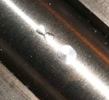
5068 forum posts 3 photos | Don't underestimate the MKl eyeball though. Believe it or not it's accurate to 0.001" unless registered blind that is and then you can use your white stick as a wiggler
The pip on the left is done by an endmill / slot drill and has been very accurately been placed on centre using a DRO.
The pip on the right has been done with the same cutter but the work has been wound in 0.001" according to the DRO.
The difference is noticeable. |
| Ian P | 25/01/2014 21:58:27 |
2747 forum posts 123 photos | John Wound in 0.001" In which direction? It looks like the depth of cut might be that but without knowing the work diameter its hard to be sure. If its distance is to the centreline what was the DRO referenced off?, or how can you be sure its so accurate? As you infer eyeballs are pretty good, and yes you can observe 0.001" differences but its then working in comparator mode, if you are trying to crossdrill a round bar the unaided eye is only going to achieve that accuracy if the bar is maybe 0.25mm diameter and the drill is 0.01 diameter (watchmaker sized parts) Ian P |
| John Stevenson | 25/01/2014 22:03:56 |
5068 forum posts 3 photos | Ian, Does it matter ? Can you not see that the pip on the right is not in the centre ? |
| Ian P | 25/01/2014 23:08:52 |
2747 forum posts 123 photos | No it doesn't matter but what I was trying to say is that I can see they are not in line but how do we know which one is correct? The laser device looks to be a good way of getting it on the bar centre without even having to know what the diameter is. What is not so obvious is what degree of accuracy can be garnered from the usual irregularly shaped laser spot. Ian |


Please login to post a reply.
Magazine Locator
Want the latest issue of Model Engineer or Model Engineers' Workshop? Use our magazine locator links to find your nearest stockist!
Sign up to our Newsletter
Sign up to our newsletter and get a free digital issue.
You can unsubscribe at anytime. View our privacy policy at www.mortons.co.uk/privacy
Latest Forum Posts
- *Oct 2023: FORUM MIGRATION TIMELINE*
05/10/2023 07:57:11 - Making ER11 collet chuck
05/10/2023 07:56:24 - What did you do today? 2023
05/10/2023 07:25:01 - Orrery
05/10/2023 06:00:41 - Wera hand-tools
05/10/2023 05:47:07 - New member
05/10/2023 04:40:11 - Problems with external pot on at1 vfd
05/10/2023 00:06:32 - Drain plug
04/10/2023 23:36:17 - digi phase converter for 10 machines.....
04/10/2023 23:13:48 - Winter Storage Of Locomotives
04/10/2023 21:02:11 - More Latest Posts...
- View All Topics
Support Our Partners


Shopping Partners
Subscription Offer

Latest "For Sale" Ads
- Reeves** - Rebuilt Royal Scot by Martin Evans
by John Broughton
£300.00 - BRITANNIA 5" GAUGE James Perrier
by Jon Seabright 1
£2,500.00 - Drill Grinder - for restoration
by Nigel Graham 2
£0.00 - WARCO WM18 MILLING MACHINE
by Alex Chudley
£1,200.00 - MYFORD SUPER 7 LATHE
by Alex Chudley
£2,000.00 - More "For Sale" Ads...
Latest "Wanted" Ads
- D1-3 backplate
by Michael Horley
Price Not Specified - fixed steady for a Colchester bantam mark1 800
by George Jervis
Price Not Specified - lbsc pansy
by JACK SIDEBOTHAM
Price Not Specified - Pratt Burnerd multifit chuck key.
by Tim Riome
Price Not Specified - BANDSAW BLADE WELDER
by HUGH
Price Not Specified - More "Wanted" Ads...
Get In Touch!
Do you want to contact the Model Engineer and Model Engineers' Workshop team?
You can contact us by phone, mail or email about the magazines including becoming a contributor, submitting reader's letters or making queries about articles. You can also get in touch about this website, advertising or other general issues.
Click THIS LINK for full contact details.
For subscription issues please see THIS LINK.
Digital Back Issues


Donate

 Register
 Log-in
Model Engineer Magazine
- Percival Marshall
- M.E. History
- LittleLEC
- M.E. Clock

ME Workshop
- An Adcock
- & Shipley
- Horizontal
- Mill

Subscribe Now
- Great savings
- Delivered to your door

Pre-order your copy!
- Delivered to your doorstep!
- Free UK delivery!
All Forum Topics > Workshop Tools and Tooling > Rotary Laser centre finder