
Tachometer design
Views on tachometer design
| Les Jones 1 | 16/01/2010 12:45:14 |
| 2292 forum posts 159 photos | Hi All, I have built tachometers for my lathe mill and drill press in the past. The design was governed by an easy way to sense the rotation and what bits I had lying around at the time. I was wondering if there would be any interest in a tachometer that could cope with between 1 and 99 pulses per rev. If there was I do not know if it would be best to try to get the design published in "Model Engineers Workshop" (Where it would more likely interest readers.) or in "EPE" electronics magazine who are more set up to provide printed circuit boards and programmed PIC's One pulse per rev is useful if there are no gears in the drive train. One pulse per rev can be sensed easily with a reflective marker and optical sensor. If there are gears in the drive train a hall effect gear tooth sensor is easy to use. The display would be a four digit LED display reading from about 30 RPM to 9999 RPM Regards Les (Ormskirk Lancs.) |
| Martin W | 16/01/2010 13:42:51 |
| 940 forum posts 30 photos | Hi Les
I can see what your problem is as the project falls between the two disciplines. How about doing a detailed write up of the electronics with PIC programming, board layout, various sensor interfacing etc. as a stand alone project and submit this to an electronics journal. Then referring to this do an article detailing the fit of this system to various machines and submit this to something like MEW. That way if anybody wants to fit this design to a machine then the information is available to them.
I have an electronics background, which I assume you do as well, and find myself with a similar dilemma regarding some suggestions made in these forums. One can sometimes see a better way of doing things, electronically that is, but one hesitates to get involved in supplying this information as it crosses disciplines and other's skill levels in are not known. Personally I would like to see your system however it gets to print
You never know you might be able to publish in both and get two payments!!
 Good luck.
Martin W Edited By Martin W on 16/01/2010 13:44:33 |
| Les Jones 1 | 16/01/2010 15:08:33 |
| 2292 forum posts 159 photos | Hi Martin, I have put the design that this tach will be based on on one of the Yahoo technical forums (X series mills I think) That one is for one pulse per rev. It basically measures the time of one revolution and then calculates the RPM from that. All I plan to do is to add a single push button to enable the number of pulses per rev to be set. The plan is this. To enter setup mode power up the unit with the push button pressed. When it is released it will be in setup mode and will display the current pulses per rev value. Pressing the button again will cause this value to increment at a rate of about one per second. when the required setting is reached the button will be released. About 5 seconds after the button is released this value will be stored to EEPROM. (Non volatile memory.) The unit is then powered off to get out of setup mode. When it is next powered on the new value in EEPROM will be used in the calculation. The circuit is very simple using a PIC16F628A, a four digit LED display, a 20 Mhz crystal, four transistors and a few resistors and capacitors. Having to building a programmer I think would put people off which is why I thought of the electronics magazine route. I was not thinking of the payment side just a way of making it easy for a non electronics person to build. I just built mine on stripboard. (Or Veroboard as it used to be called.) I will wait and see what others think before deciding which way to proceed. Regards Les (Ormskirk Lancs.) |
| Steve Garnett | 16/01/2010 16:04:37 |
| 837 forum posts 27 photos | I can concur with what Martin W said, but if you really aren't interested in the payment side of it as such, then surely the other way to approach this is to set up a web page with the design on, pictures, background info, whatever, and simply sell people a pre-programmed PIC, or even get a small PCB made up for it, and sell that as well. It gets you around pretty much all of the problems, I think; there are quite a few designs for one thing or another presented around the web this way, and many of them are quite successful. Even if you didn't want to handle the PCBs yourself, producing a set of files that could be sent to one of the one-off prototyping services by anybody wanting to build one might be another way to handle this. Of course, the other mag that might well consider something like this is Elektor - after all, they've published all the details of a small CNC mill, and got a manufacturer to sell a kit of it, haven't they? It's rather more up their street than EPE, however you look at it. |
| Martin Cottrell | 16/01/2010 16:38:52 |
| 297 forum posts 18 photos | Hi Les,
I think an article in MEW detailing the construction of your tachometer would be a great idea. I for one don't have a clue as to how electronic devises work but would be quite capable of soldering a few components together on a board if someone supplied me with the information on where to place them along with some guidance to avoid pitfalls and damage to sensitive components whilst soldering.
If I recall correctly there have been other constructional series in MEW involving some quite complex electronics such as the spark erosion machine and a CNC mill. As such I think your tachometer would be a very suitable project to include in the pages of MEW and would be of interest to many of us.
Regards, Martin. |
| Les Jones 1 | 16/01/2010 18:41:50 |
| 2292 forum posts 159 photos | Hi Martin (C), I have only read a few copies of MEW I have only bought it when I have seen that it contains an article of interest to me. The spark erosion machine sounds interesting. I experimented with it in the mid 1960's without much success. Here are some pictures of the original version which is only for one pulse per revolution. The only difference in the hardware for the version that supports different numbers of pulses per rev is the addition of a push button switch. The rest will be done by re writing the firmware. 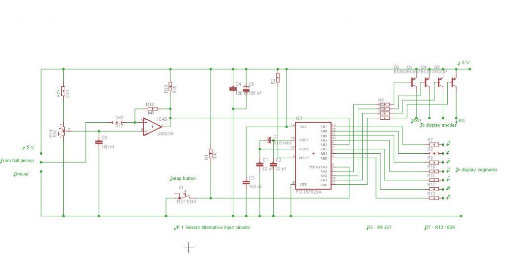 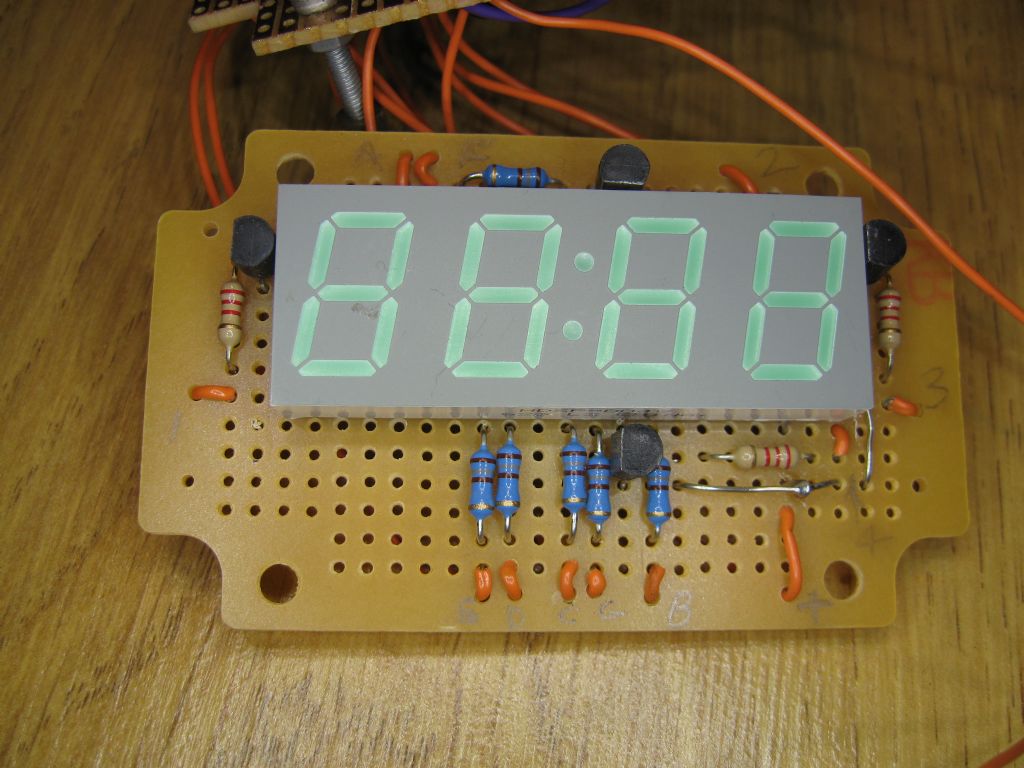 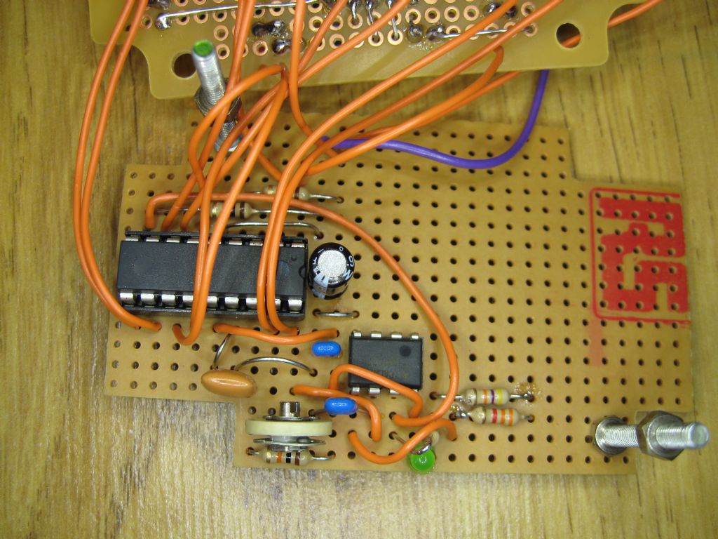 I do not think the schematic is readable but it should give an idea of how simple the circuit is. Les. |
| Steve Garnett | 16/01/2010 19:48:15 |
| 837 forum posts 27 photos | I can see the schematic just fine - it's pretty clear. The whole thing looks eminently suitable for a small PCB - doesn't even need to be double-sided, does it? The obvious advantage of this would be that it reduces the possibility of errors in construction, but still gives the satisfaction of saying that you built it yourself. I'm not actually anti-stripboard, but it's got to the point now where it's remarkably cheap to get small boards made up - I would have thought that they'd be about £5-6 each, or thereabouts, although you'd have to make 4 or 5 at a time to get the price to that level. |
| Geoff Theasby | 16/01/2010 19:54:34 |
| 615 forum posts 21 photos | I think we are all barking up the wrong tree here.
We are model engineers, shouldn't we be thinking about a mechanical tachometer?
When I was much younger, I dismantled a car speedometer. This was driven by a circular weight, pivoted on a shaft. When the shaft spun, the weight tried to assume a position at right angles to the shaft axis.
Surely, the displacement of this weight could be used to operate a dial test indicator so as to give a visual, mechanical readout of speed?
How was this done by the makers of Dynamometer cars, especially for model railways? I know that a few were made.
I have some ideas on how this might be done, but what do people think?
Regards
Geoff
|
| Steve Garnett | 16/01/2010 21:41:58 |
| 837 forum posts 27 photos | Posted by Geoff Theasby on 16/01/2010 19:54:34: I think we are all barking up the wrong tree here. We are model engineers, shouldn't we be thinking about a mechanical tachometer? When I was much younger, I dismantled a car speedometer. This was driven by a circular weight, pivoted on a shaft. When the shaft spun, the weight tried to assume a position at right angles to the shaft axis. Well, I can understand where you're coming from with this, but when it comes to universal applicability, I think that a mechanical device doesn't really have a lot going for it these days. And, they inevitably consume power. So if I want to fit one to a relatively small lathe which isn't exactly over-imbued with power, as well as having to arrange a power take-off, I'm going to sap a some of it too, just to find out very approximately how fast it's going. And I don't know how old the speedometer you took to bits was, but since about 1910 the mechanical ones have pretty much all used the rotating magnet/aluminium disc eddy current method. This would be mechanically quite easy to implement, and doesn't pose much of an extra load, but is still inherently no more accurate than about +/- 5%, and that's in the good part of the range; at lower speeds it becomes progressively less accurate - to the point where you might as well guess how fast the shaft was going. So from a pragmatic point of view, I'd still vote for Les's small, relatively accurate, virtually zero-load sensor and a small bit of electronics, I'm afraid, although I'd still be intrigued to see how small and accurate you could make a lightly-loaded mechanical tach - but purely out of curiosity. And I'm not quite sure why being a model engineer (which, incidentally, I hesitate to describe myself as, in comparison with many here) would preclude using electronic devices in conjunction with mechanical ones? Especially when it comes to the means of production, rather than the end itself? I do quite a lot of experimental small-scale electromechanical engineering, and as far as I'm concerned there is absolutely no conflict of interest between the disciplines at all; in many ways they are rather complimentary, especially when it comes to things like the means of indication. Just because something wasn't done like this in the past doesn't mean that it wouldn't have been if it had been feasible, I'm absolutely sure. |
| Geoff Theasby | 16/01/2010 22:52:53 |
| 615 forum posts 21 photos | OK, I see what you are getting at.
At the same time, I'm not talking about a constant speed measurement.
One might take a test to check the speed momentarily. It could be calibrated from a lathe with a known speed range.
After all, we wouldn't need to know the speed that accurately, only an infrequent test, so the power needed to drive the system wouldn't be a constant drain. After all, we don't need to know the instantaneous speed of a lathe with an electronic speed readout, or even a gearbox with fixed speeds. We set the speed and leave it whilst we do the work.
I, personally, am quite happy mixing electronics with mechanics, as I am a fully qualified radio amateur, but I appreciate that there are likely to be many others who are not at home with electronics.
Regards
Geoff |
| Steve Garnett | 16/01/2010 23:46:52 |
| 837 forum posts 27 photos | Posted by Geoff Theasby on 16/01/2010 22:52:53: At the same time, I'm not talking about a constant speed measurement. One might take a test to check the speed momentarily. It could be calibrated from a lathe with a known speed range. After all, we wouldn't need to know the speed that accurately, only an infrequent test, so the power needed to drive the system wouldn't be a constant drain. After all, we don't need to know the instantaneous speed of a lathe with an electronic speed readout, or even a gearbox with fixed speeds. We set the speed and leave it whilst we do the work. I, personally, am quite happy mixing electronics with mechanics, as I am a fully qualified radio amateur, but I appreciate that there are likely to be many others who are not at home with electronics. Geoff, I think that one of the reasons that people want to fit tachometers is because they do want to know what the speed is all the time. For instance, if you retrofit a three-phase motor to an old machine and power it with an electronic inverter, one of the many new advantages you get is the option of continuous speed change. And there have been numerous reports now of people varying the speed as they cut (both with lathes and mills) for the best finish, and also checking to see how much it falls under load. In the first instance, you can make a note for yourself of where the machine/tooling is happiest, and next time you cut the same material in a similar way you'll have a much more accurate starting speed. Also, noting any speed drop in real time whilst cutting (not all people can spot this easily by listening) gives you a good idea that perhaps you should reduce either the rate or depth of cut slightly - and give you good, immediate feedback that the correct speed has been restored after you've made the changes. I've used a calibrated strobe in the past to establish running speeds of machines, and I have to say that it's a bit of a pain to do it like that. Also, I have several machines of my own that I'd like to fit tachos to, so if I can find a nice cheap way to do this independently for each one (and it looks like Les's system can easily achieve that), then I'd call it a good result, and the case for doing it this way is, in my view, overwhelming. Yes, I could start over and create my own, but I can't see any point in re-inventing the wheel, and anyway, I don't like programming very much - I'm an old analogue person, really. As for the people who aren't at home with electronics, I agree - which is why I think that providing a PCB (or a plan for it) is the way to go. I would have thought that most model-makers wouldn't have too much difficulty soldering some through-hole components onto a PCB, and if they do, then this would be a good project to learn on - relatively straightforward from a construction point of view and with a high probability of first-time success. Heck, this one would be simple enough to get people to etch their own PCBs, if they're feeling brave... Anyway, that's my take on it! Steve |
| Ian S C | 17/01/2010 02:16:09 |
 7468 forum posts 230 photos | Can't remember when it was,but an electronic tacho was an artical over a number of issues of ME(its a few years back),it gave the whole works from the electronics to the mechanics.I havn't built it,I use a simple system of a 125t gear and a worm with a stop watch,but electronic would be better by far,I have used my frequency meter.I imagine that those with variable speed machines would find it handy to know what speed it is running at,or do these things have a tacho?Ian S C Edited By Ian S C on 17/01/2010 02:18:01 |
| Michael Cox 1 | 17/01/2010 12:59:32 |
| 555 forum posts 27 photos | With the price of digital electronic frequency meters now around the £10 mark (inc shipping) from China it is easier to simply use a disc with 60 holes attached to the rotating spindle with an opical sensor to give a reading directly in RPM. A project based on this was presented in MEW in 2009 or 2008.
An even simpler solution is to buy a cycle computer and fix a magnet to the shaft. I have used this solution using a cycle computer from Wilkinson's at a cost of £6.99. The unit gives a direct readouut in RPM.
Mike |
| Peter G. Shaw | 17/01/2010 16:03:14 |
 1531 forum posts 44 photos | Hi folks, Recently I used a cycle speedo from Halfords to measure the rpm of both my lathe and mill. There were problems, eg fastening the magnet onto the rotating shaft, above 30kph (equivalent to 300rpm) it only measured every 5rpm, and above 60kph (I think) it only measured every 10rpm whilst above another speed it became intermittent. Calibration involved setting the device to kph and setting it up as if it was measuring the speed of a particular sized wheel (1777 was the value I used I think). With these values it gave direct rpm readings. Changing the wheel size value means that the device can be used for different rpm ranges, but then it will involve some calulations. On the plus side, the device was readily available (removed from the bike to have a new battery fitted!), and reasonably easy to use. And it met my requirements. Regards, Peter G. Shaw |
| KWIL | 17/01/2010 16:26:21 |
| 3681 forum posts 70 photos | I have 4 machines using inverters. I have a 10 turn speed setting linear potentiometer on each. On the Myford S7 for example, if I choose a particular pulley setup, then 50% [indicated by 50 on the dial] does in fact give me half way up the speed range. I have checked the speeds using strobe disc as [published in MEW some time ago] and latterly using a strobe meter. Frankly you do not need an exact speed setting anyway, but this method is very close. If you only have coarse < 1 turn dial as fitted on some commercially available kits then a tacho could be useful. In normal use I can get within a few percent of any desired speed without having a digital readout. Regards K |
| Martin Cottrell | 17/01/2010 20:37:45 |
| 297 forum posts 18 photos | Hi Les,
Having read all the arguements for and against, I still think it would be a useful project to write up for MEW. Assuming it could be built for say under £15-20 and does not require other testing equipment to calibrate it then I would have thought it would be of interest to quite a few readers.
I would have a chat with our editor, David Clark, because when all is said and done he is the one who will decide whether or not the article is appropriate.
Good luck!
Regards, Martin. |
| Steve Garnett | 17/01/2010 22:38:43 |
| 837 forum posts 27 photos | I think that I agree with Martin. I had a look at some of the other options, and I can't see anything else that is simple to make, easy to hook up and cheap, and could be easily mounted in an existing case and, quite importantly for me, uses LEDs rather than a LCD display. The closest I can get is the module that Quasar sell - and it's just about cheap if you buy 5 of them. You can look at it here, but I have to say that it's going to require an input modification, so even this isn't quite straightforward. If anybody knows of any others that I've missed, I'd be delighted to know about them. Steve |
| Steve Garnett | 18/01/2010 10:41:48 |
| 837 forum posts 27 photos | Posted by Michael Cox 1 on 17/01/2010 12:59:32: With the price of digital electronic frequency meters now around the £10 mark (inc shipping) from China it is easier to simply use a disc with 60 holes attached to the rotating spindle with an opical sensor to give a reading directly in RPM. A project based on this was presented in MEW in 2009 or 2008. I checked - it was Feb 2009, so not that long ago at all. Also, I had a look on ebay, and discovered that I can get a panel meter with approximately the specification I outlined above for about £15, with an even cheaper possibility also, so I might give that a go. Thanks - Steve Edited By Steve Garnett on 18/01/2010 10:44:09 |
| Les Jones 1 | 18/01/2010 11:16:12 |
| 2292 forum posts 159 photos | Hi All, All the methods suggested are good when the situation suits. Using the frequency meter to count 60 pulses per rev is ideal if it is easy to fit a disk with 60 holes and optical sensor or a 60 tooth gear and hall effect gear tooth sensor. The cycle computer I think is the cheapest method if it can accommodate the speed range required. The problem mentioned about mounting the magnet can be eliminated by using a reflective optical sensor and signal level converter. The first rev counter I made for my lathe used the frequency meter method. The lathe had a 45 tooth gear on the end of the spindle so all that was required was to count the number of pulses in 1.333 seconds. (60 divided by 45) The mill had a gear with 34 teeth which would have required measuring the number of pulses in 1.765 seconds (60/34) I considered that this would be too slow an update rate so I modified the design to get a pulse of each edge of the tooth so this brought the sample time down to about 0.8 seconds. On various forums there had been questions about rev counters for use with one pulse per rev. I also wanted a rev counter on my drill press which did not have any gear teeth to sense. For this I needed the method that must be used by a cycle computer which is to measure the time of one revolution and calculate RPM from that. I actually counted the number of 0.4uS pulses that occurred in one revolution and divided this into 150000000 which is the number of 0.4 uS in one minute. By adding some code to divide the reading by the number of pulses per rev sensing any number of pulses per rev can be used. I then thought of a way to enter the number of pulses per rev using one push button connected to a spare input on the PIC chip. Hence the question about interest in the design. Yesterday I have got the unit basically working but now need to test that there are no problems with any pulses per rev setting at any input speed. (Overflow of numbers in the calculations or other problems I have not even thought of.) I would be interested in information on the cycle computers in terms on the maximum and minimum wheel sizes they can be configured to work with and the maximum speed they can display. (Also the number of digits in the display.) As the method of operation of my design is basically the same as a cycle computer if they can cover the required speed range then my design is redundant. I think the components for my design will cost between £6 and £10 plus a PCB, box and power supply. I think someone asked about calibration. This is not required as the time measurement is controlled by a crystal whose accuracy is quoted in parts per million. Steve, I am not sure about how the Quasar design works as though the give the schematic they do not give the integrated circuit numbers. I SUSPECT that it uses a "charge pump" to convert frequency into voltage then displays that voltage as RPM's Sorry all about the length of this reply. Les. |
| Lawrie Alush-Jaggs | 18/01/2010 11:36:11 |
 118 forum posts 32 photos | Hi Les Jones 1 I can't talk about the counter circuitry but if you want to find a nice accurate disk and light source look no further than a clagged injet printer. You will find that there is a very nice Mylar disk with anywhere between 150 and 360 light slits in them and sitting ajacent to it will be a light sensor and source. |
Please login to post a reply.
Want the latest issue of Model Engineer or Model Engineers' Workshop? Use our magazine locator links to find your nearest stockist!
Sign up to our newsletter and get a free digital issue.
You can unsubscribe at anytime. View our privacy policy at www.mortons.co.uk/privacy
- hemingway ball turner
04/07/2025 14:40:26 - *Oct 2023: FORUM MIGRATION TIMELINE*
05/10/2023 07:57:11 - Making ER11 collet chuck
05/10/2023 07:56:24 - What did you do today? 2023
05/10/2023 07:25:01 - Orrery
05/10/2023 06:00:41 - Wera hand-tools
05/10/2023 05:47:07 - New member
05/10/2023 04:40:11 - Problems with external pot on at1 vfd
05/10/2023 00:06:32 - Drain plug
04/10/2023 23:36:17 - digi phase converter for 10 machines.....
04/10/2023 23:13:48 - More Latest Posts...
- View All Topics


- Reeves** - Rebuilt Royal Scot by Martin Evans
by John Broughton
£300.00 - BRITANNIA 5" GAUGE James Perrier
by Jon Seabright 1
£2,500.00 - Drill Grinder - for restoration
by Nigel Graham 2
£0.00 - WARCO WM18 MILLING MACHINE
by Alex Chudley
£1,200.00 - MYFORD SUPER 7 LATHE
by Alex Chudley
£2,000.00 - More "For Sale" Ads...
- D1-3 backplate
by Michael Horley
Price Not Specified - fixed steady for a Colchester bantam mark1 800
by George Jervis
Price Not Specified - lbsc pansy
by JACK SIDEBOTHAM
Price Not Specified - Pratt Burnerd multifit chuck key.
by Tim Riome
Price Not Specified - BANDSAW BLADE WELDER
by HUGH
Price Not Specified - More "Wanted" Ads...
Do you want to contact the Model Engineer and Model Engineers' Workshop team?
You can contact us by phone, mail or email about the magazines including becoming a contributor, submitting reader's letters or making queries about articles. You can also get in touch about this website, advertising or other general issues.
Click THIS LINK for full contact details.
For subscription issues please see THIS LINK.


 Register
 Log-in
Model Engineer Magazine
- Percival Marshall
- M.E. History
- LittleLEC
- M.E. Clock

ME Workshop
- An Adcock
- & Shipley
- Horizontal
- Mill

Subscribe Now
- Great savings
- Delivered to your door

Pre-order your copy!
- Delivered to your doorstep!
- Free UK delivery!