
Skomo Tablr Saw - Brook Crompton motor wiring weirdness
Odd wiring on Brook Compton motor.
| Bob Miller 2 | 22/12/2021 23:09:01 |
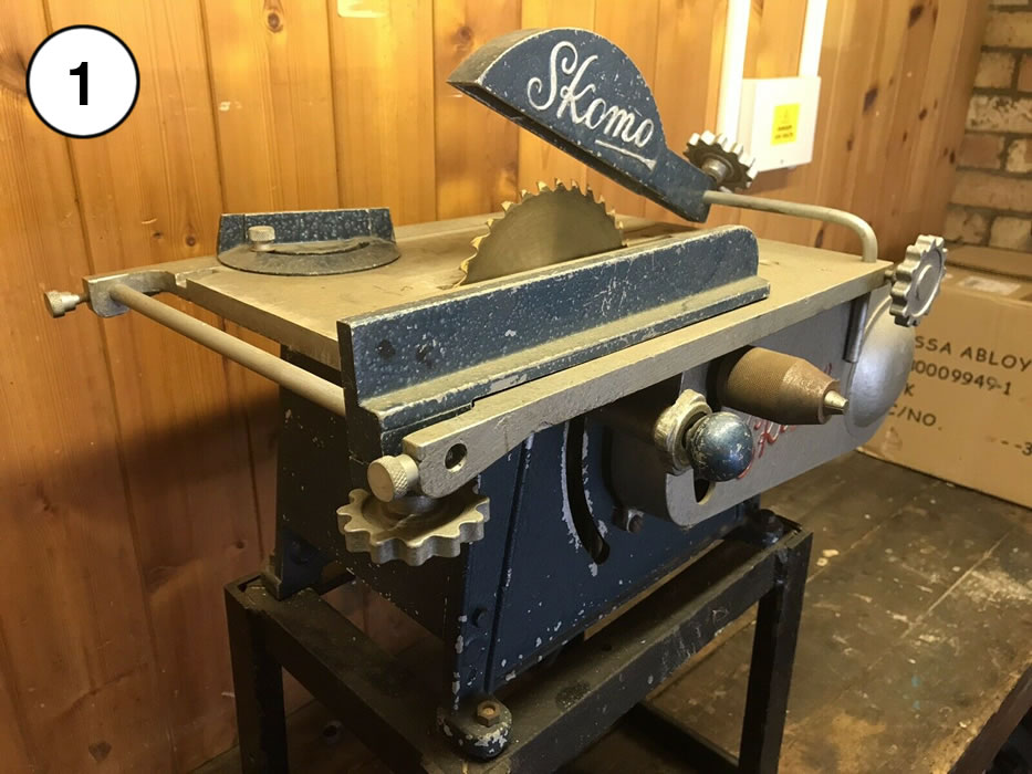
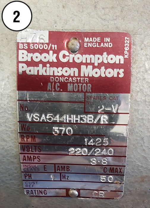
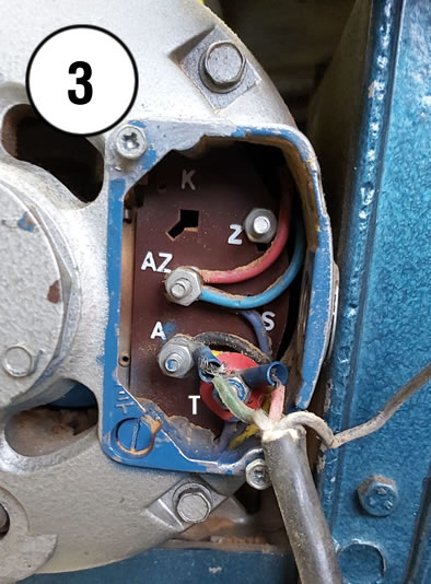
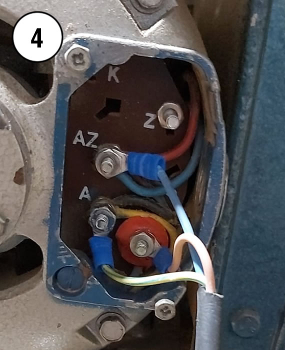
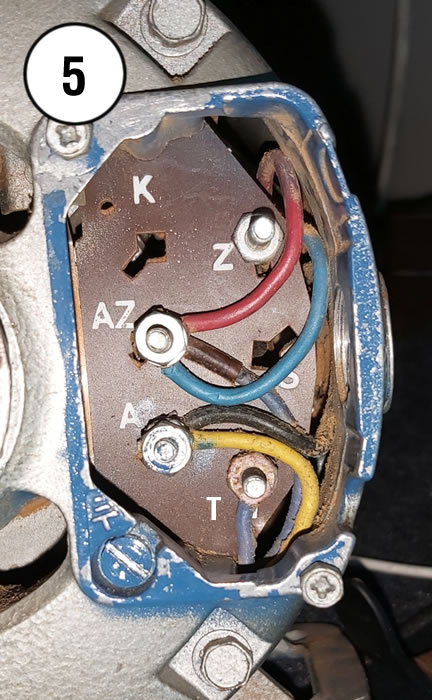
| 2 forum posts | Hi I wonder if anyone can help. A while ago, for very little money, I bought a cool little bench saw (Photo 1) with a Brook Compton motor (Photo 2) from the son in law of a deceased amateur carpenter. I saw the saw working at the home of the late amateur carpenter and was looking forward to using the saw at home. The saw sat in my garage for a few months before I got around to using it. The first time I plugged it in, the saw tripped the RCD it was plugged into. I opened the panel on the back of the motor to see if I could see what was going on (see photo 2). I saw 6 terminal points : From top to bottom : K, Z, AZ, S, A, T. Terminals K & S are blank. The plug was wired: A to Earth, T to Live and I found Neutral loose in the compartment; not connected to anything, assuming it came off on the trip home. Z only has 1 nut, so I assumed the neutral wire had fallen off of AZ as the end looked flat, as if squeezed between 2 nuts (no ring crimp attached and no empty ring crimp on any of the terminals) so tried wiring neutral to that as a test (Photo 3) using new cable and mains plug, wiring earth to A and Live to T as it was wired originally, plugged into an RCD socket all the while. Certainly looked odd to me, what with no earth to the case (bottom left of the compartment) The RCD tripped again. I removed my wiring to try and make sense of it (Photo 5) I added the letter "T" to phpt, as the printed letter is obscured by the bottom wire. I have seen similar Crompton motors in other posts on line, but with only 4 wires ( T and Z to the switch and AZ and A to run) (**LINK**/ but this motor has 6 wires. The seller knows nothing about this saw. He thought the only way to use it was to plug it in... it runs.. unplug it... it stops. So I was just intending on putting a switch box in the cable, until this became very confusing. It looks like A definitely isn't an earth, so how on earth was it running at point of sale? Any pointers would be very helpful. Confused Bob.
|
| not done it yet | 23/12/2021 08:22:16 |
| 7517 forum posts 20 photos | Dunno, but I would strongly suggest the green/yellow wire should be connected to that screw at the left bottom of the pics (marked as earthing point). Seems to me like a dummy has been wiring it! Little wonder it is tripping a RCD if no current through the neutral. I suspect it might be running quite happily from live to earth! |
| Ian Parkin | 23/12/2021 08:24:00 |
 1174 forum posts 303 photos | Does the cover for the terminals not have the wiring diagram for your motor printed on it? |
| Michael Gilligan | 23/12/2021 09:20:26 |
 23121 forum posts 1360 photos | This looks a good place to start : **LINK** https://www.instructables.com/Wiring-up-a-Brooke-Crompton-single-phase-lathe-mot/ MichaelG. |
| DiogenesII | 23/12/2021 09:22:56 |
| 859 forum posts 268 photos | ..er, electricity isn't my profession, so if someone would be kind enough to check and confirm.. ..don't do anything 'til then! ..a typical 'Brooks' set-up would be; A - 'Run' winding - Black - AC Neutral AZ - 'Run' winding - Red - AC Live Z - 'Start' winding - Yellow - AC Neutral T - 'Start' winding - Blue - AC Live SO, 'as is' it looks like the dark blue 'jumper' wire between AZ and T should be removed and; A, (Black and Yellow) should receive AC Neutral AZ, (Red and Blue) should receive AC Live The Earth terminal on the case must be earthed. (I think ideally, the Z and T terminals should be occupied by the Yellow & Blue wires, bridged to A and AZ, respectively - this will make it easier to transpose them if the motor runs backwards on starting). This ought to establish 'running from a switched socket' for testing purposes, hopefully someone will advise on a safe switching system, you mustn't leave it like that especially if there's even a remote possibility of others entering your workshop.. |
| Ady1 | 23/12/2021 10:17:30 |
 6137 forum posts 893 photos | Might help I run mine on an RCD if mains is brown-live yellow-earth blue-neutral then it looks like AZ and A are your live/neutral swap for direction and T is your earth Just keep it on the RCD and wear thick gloves when you plug it in lol Edited By Ady1 on 23/12/2021 10:32:14 |
| Stuart Smith 5 | 23/12/2021 11:16:10 |
| 349 forum posts 61 photos | Bob I would suggest you get an electrician or someone with electrical knowledge to sort this. Some of the ‘helpful’ suggestions might be dangerous! At the very least, the casing should be connected to the incoming earth wire. Stuart |
| Ian P | 23/12/2021 11:45:17 |
 2747 forum posts 123 photos | Posted by Stuart Smith 5 on 23/12/2021 11:16:10:
Bob I would suggest you get an electrician or someone with electrical knowledge to sort this. Some of the ‘helpful’ suggestions might be dangerous! At the very least, the casing should be connected to the incoming earth wire. Stuart +1 |
| noel shelley | 23/12/2021 12:30:02 |
| 2308 forum posts 33 photos | The earth wire - yellow/green MUST be connected to the frame of the motor NOT any of the terminals on the terminal block ! IT IS CLEARLY MARKED IN ONE PICTURE ! Diogenes is almost there ! BUT T is the thermal/ overload switch - a simple thermal switch that offers some protection. Black and red are the run windings, blue and yellow the start windings. You make no mention of a capacitor so it would appear to be split phase starting. The centrifugal switch is in the yellow line. SO ! Live to T if the switch is good live will appear on AZ. Neutral will go to A ! The terminal block was used on many small motors and some terminals were not fitted and those that were, were not always used ! This motor being a case in point. Tubal Cains book The Model Engineers Hand book, is worth buying if only for the wiring diagrams for small motors, it includes one that many say does not exist, I came accross 2 motors of that type in 12months. If when wired up it runs in the wrong direction, then reverse the BLUE and YELLOW start winding wires. I hope this helps, Noel. Edited By noel shelley on 23/12/2021 12:32:58 |
| john fletcher 1 | 23/12/2021 12:44:59 |
| 893 forum posts | First of all, have the motor insulation tested, its been out of use for some time and possibly partly full of damp saw dust, which needs sucking out, not blown in via damp compress air. Others have already have described which coloured wire goes to which terminal, but when you do an initial run test note the start winding pair which might need moving over (reversing), as the motor is running in wrong direction. You also need a proper motor starter with No volt release and overload protection, plenty of them available on the net or a club member. Nice looking machine, but be very careful with a saw bench, they can bight. John |
| Emgee | 23/12/2021 13:56:39 |
| 2610 forum posts 312 photos | Good advice in the last 2 posts from Noel and John, there appears to be a lot of wood dust within the motor housing, even in the terminal connector block. Emgee |
| Martin Johnson 1 | 23/12/2021 16:16:07 |
| 320 forum posts 1 photos | I have a copy of "Installation and Maintenance of Electric Motors" by BCPM. The wiring diagram for the VS series motors shows terminal AZ as line, A as neutral and earth is the case as previously noted. The motor is a split phase type with starting windings controlled by a centrifugal switch. To reverse rotation, swap the internal yellow and blue wires between A and AZ. Internal wires red and black should stay where they are. It looks as though your motor has a thermal switch to prevent overload - that should be wired in series on the line input. Not clear from the photos, but if you can get a proper cable gland into the housing to grip and take mechanical strain off the power cord, it would be a lot better. If you can't use the mouse hole as presently used, but anchor the cord nearby to the machine frame. Martin |
| SillyOldDuffer | 23/12/2021 17:14:26 |
| 10668 forum posts 2415 photos | Ha, I'm feeling smug because my suggestion fits with Martin and Noel, viz: Green/Yellow (Earth) to terminal marked ⏚ on the frame Brown (Line) to 'T' Blue (Neutral) to 'A' If the motor fails to start, it may be because the thermal cut-out on 'T' has died, in which case try connecting Brown to 'AZ'. If this bodge is necessary take care not to overheat the motor with extended heavy cutting. Plastic ratchet cable ties can be used for strain relief. (In this example the black grommet fits a U shaped slot in an outer box, and the cable tie stops the wire being pulled through the grommet.)
Dave
|
| Bob Miller 2 | 23/12/2021 18:10:41 |
| 2 forum posts | Thank you everybody for your massively helpful replies. Safety wise, I wasn't touching the machine while testing, only the switch of the socket that the RCD socket is plugged into. I wired live to AZ and neutral to A and earthed the case via the blue screw bottom left. The machine now runs. I can't believe how quiet it is. Having read the replies, I will move live to the T terminal, if that is a thermal switch. To reply to each above: not done it yet: I can't figure how the original owners consumer unit wasn't tripping while in that configuration. The sockets looked normal to me, but maybe there was something else the owner had been up to. Ian Parkin: No diagram anywhere on the motor, only the panel in the photo. Michael Gilligan: Yes, that's the same link in my post. A bit different, but very helpful. DiogenesII: That's exactly as I have it now, which I feel better about having read your reply. Yes, I have a proper switch box to put inline between the machine and socket and will make it all sensible and safe. Having read noel's reply, I will use a proper motor starter instead. Ady1: I will run this machine on the RCD, even after I have my consumer unit professionally fitted to my workshop with another RCD in the consumer unit in my house. Stuart Smith 5 & Ian: Yes, I will get the same certified chap who is coming to install my workshop consumer unit, to take a quick look, just tho be safe. noel shelley: Sure, this is done,. I was just trying to mimic what the original owner had done for testing. I'd not even considered a motor starter. Iremember seeing one of these saws sold previously on eBay with what I thought was just a huge switch next to it, now I know it was a motor starter. £40 to £50... I'll get reading. john fletcher 1 & Emgee: Great point abiout the sawdust, I'll give it a thorough going over. Martin Johnson 1: I was looking at glands and similar ealier and after reading other replies above, maybe mounting a board on the side of the machine to hold the cable and motor starter. I can probably 3d print and cast a rubber gland myself if I can't find one small enough. SillyOldDuffer: I was digging around for my cable ties for a temporary strain relief earlier too. I'll try the T terminal tomorrow morning.
Have a great Christmas. Bob
|
| Michael Gilligan | 23/12/2021 18:34:27 |
23121 forum posts 1360 photos | Posted by Bob Miller 2 on 23/12/2021 18:10:41:
[…] Michael Gilligan: Yes, that's the same link in my post. A bit different, but very helpful. […] . Apologies, Bob … I missed that significant point MichaelG. |
| noel shelley | 23/12/2021 19:26:04 |
| 2308 forum posts 33 photos | Hi Bob, Glad it works ! An RCD is a device that will check leakage, if in and out differ by more than normally 30Ma it will drop. A no- volt release once set will hold until A) it's turned off or B) the power fails, at which point it will turn off and will only restart when re set ! A Direct On Line starter is usually both No volt and motor protector BUT To protect the motor the overload must be rated and set for the motor Full Load Amps, a failure to observe this will not give protection, or constantly keep dropping out. If buying second hand check that the contactor coil is of the right voltage, for single phase 240V or close and covers the right current range for your motor. When the workshop is being wired up, wire it on a fused circuit to the shed BUT NOT on the house RCD, fit a consumer unit in the workshop with all the circuits fused and on an RCD of it's own. This avoids the house being taken out if a fault develops and all the problems that may ensue. Good Luck. Noel |
| Frances IoM | 23/12/2021 19:33:15 |
| 1395 forum posts 30 photos | individual RCBOs (ie 1 per circuit) avoid problem of losing lights if all circuits in shed are fed from 1 RCD which trips - also worth making 1 light in a workshop provide emergency lighting if power removed |
| Oven Man | 23/12/2021 22:04:12 |
 204 forum posts 37 photos | Posted by Frances IoM on 23/12/2021 19:33:15:
individual RCBOs (ie 1 per circuit) avoid problem of losing lights if all circuits in shed are fed from 1 RCD which trips - also worth making 1 light in a workshop provide emergency lighting if power removed In our old family house the light in the pantry, where all the fuseboxes were located, was on its own separate circuit. It proved its worth many times, much better than a torch or candle when you have to rewire the fuse holder. Peter |
| Alan Murray 1 | 24/12/2021 01:54:11 |
| 2 forum posts | Hi Sorry to jump in on your thread Bob. I have the same saw. I just plug mine it and it works but I was thinking of adding a motor starter to mine too. There are quite a few motor starters available. If I buy a single phase motor starter, what AMP rating should I get? May sound silly, but on the plate, Is this saw 3.8 or 3 to 8 AMP? Thanks Alan |
| John Haine | 24/12/2021 07:45:40 |
| 5563 forum posts 322 photos | 3.8 A. |

Please login to post a reply.
Want the latest issue of Model Engineer or Model Engineers' Workshop? Use our magazine locator links to find your nearest stockist!
Sign up to our newsletter and get a free digital issue.
You can unsubscribe at anytime. View our privacy policy at www.mortons.co.uk/privacy
- hemingway ball turner
04/07/2025 14:40:26 - *Oct 2023: FORUM MIGRATION TIMELINE*
05/10/2023 07:57:11 - Making ER11 collet chuck
05/10/2023 07:56:24 - What did you do today? 2023
05/10/2023 07:25:01 - Orrery
05/10/2023 06:00:41 - Wera hand-tools
05/10/2023 05:47:07 - New member
05/10/2023 04:40:11 - Problems with external pot on at1 vfd
05/10/2023 00:06:32 - Drain plug
04/10/2023 23:36:17 - digi phase converter for 10 machines.....
04/10/2023 23:13:48 - More Latest Posts...
- View All Topics


- Reeves** - Rebuilt Royal Scot by Martin Evans
by John Broughton
£300.00 - BRITANNIA 5" GAUGE James Perrier
by Jon Seabright 1
£2,500.00 - Drill Grinder - for restoration
by Nigel Graham 2
£0.00 - WARCO WM18 MILLING MACHINE
by Alex Chudley
£1,200.00 - MYFORD SUPER 7 LATHE
by Alex Chudley
£2,000.00 - More "For Sale" Ads...
- D1-3 backplate
by Michael Horley
Price Not Specified - fixed steady for a Colchester bantam mark1 800
by George Jervis
Price Not Specified - lbsc pansy
by JACK SIDEBOTHAM
Price Not Specified - Pratt Burnerd multifit chuck key.
by Tim Riome
Price Not Specified - BANDSAW BLADE WELDER
by HUGH
Price Not Specified - More "Wanted" Ads...
Do you want to contact the Model Engineer and Model Engineers' Workshop team?
You can contact us by phone, mail or email about the magazines including becoming a contributor, submitting reader's letters or making queries about articles. You can also get in touch about this website, advertising or other general issues.
Click THIS LINK for full contact details.
For subscription issues please see THIS LINK.


 Register
 Log-in
Model Engineer Magazine
- Percival Marshall
- M.E. History
- LittleLEC
- M.E. Clock

ME Workshop
- An Adcock
- & Shipley
- Horizontal
- Mill

Subscribe Now
- Great savings
- Delivered to your door

Pre-order your copy!
- Delivered to your doorstep!
- Free UK delivery!