Forum sponsored by:

First bit of Tooling
| Grant Nicholas | 15/01/2016 20:23:35 |
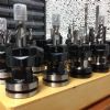 51 forum posts | Hi Gents I got a set of ER32 collets with the WM18 mill and although it had a collet spanner it did not come with a 36mm spanner for holding the collet shaft whilst doing the collet nut up. Edited By Grant Nicholas on 15/01/2016 20:25:03 |
| Johnboy25 | 15/01/2016 20:31:16 |
 260 forum posts 3 photos | Nice job 👍 |
| SillyOldDuffer | 15/01/2016 20:57:49 |
| 10668 forum posts 2415 photos | Gosh thanks Grant! I was thinking about exactly this problem today and your solution is better than the "spanner" I was going to wastefully bodge from a bit of rusty 3/8" plate tomorrow. Ta, Dave |
| Peter Krogh | 15/01/2016 20:58:53 |
 228 forum posts 20 photos | That's a much nicer bit of kit than the usual one punched out of plate. And, you did it! Pete |
| Grant Nicholas | 15/01/2016 21:05:49 |
51 forum posts | Thanks John!
|
| Harry Wilkes | 15/01/2016 21:07:36 |
 1613 forum posts 72 photos | Happy new spanner H |
| OldMetaller | 16/01/2016 08:24:33 |
 208 forum posts 25 photos | Grant, how about a short article for Neil on this piece of tooling? I have exactly the same problem with my ER32 collet chuck used on my lathe. Regards, John. |
| Michael Gilligan | 16/01/2016 08:53:01 |
 23121 forum posts 1360 photos | Posted by OldMetaller on 16/01/2016 08:24:33:
Grant, how about a short article for Neil on this piece of tooling? . +1 from 'requirement' through 'design & manufacture' to 'testing' ... it should make an excellent article. MichaelG. |
| Neil Wyatt | 16/01/2016 10:31:24 |
 19226 forum posts 749 photos 86 articles | Drop me an email if you are interested, Grant. Neil |
| Tractor man | 16/01/2016 11:20:56 |
| 426 forum posts 1 photos | Nice level of work Grant. Simple tool but well executed. Mick |
| Nick_G | 16/01/2016 11:22:43 |
 1808 forum posts 744 photos | . I like it.
Nick |
| Grant Nicholas | 16/01/2016 11:27:03 |
51 forum posts | Thanks for all the kind words gentleman. I am extremely honoured you think it worthy of a article in the MEW magazine! I have just realised how disappointed I am that I did not take any pictures of the steps in the project, I usually do this, but in this case got so absorbed in the build that I did not bother..... oh well nevermind, whats that saying about hindsight...... Grant
|
| mechman48 | 16/01/2016 12:07:25 |
 2947 forum posts 468 photos | Well done Grant, nice looking spanner. George.
|
| SillyOldDuffer | 16/01/2016 17:39:34 |
| 10668 forum posts 2415 photos | Hi Grant, Many thanks for the offer of a pdf but I think I can make one using the info you've already published. My version will be much more utilitarian than your nicely finished prototype. I might publish a photo if it's not too horrible! Cheers, Dave
|
| NJH | 16/01/2016 18:05:29 |
 2314 forum posts 139 photos | Grant The fact that you did not take pictures need not be a problem. Just make it again - taking pictures as you go. You can then either offer it as a prize or, if you are anything like me, keep it safely somewhere in case you lose the first one! Norman ( ps - the problem with the second option is remembering where the "safe place" is ! - maybe I' m a bit older than you though) |
| Muzzer | 16/01/2016 18:33:24 |
 2904 forum posts 448 photos | Nice work Grant! There's some interesting stuff in F360, especially when you consider it's free for the likes of us. Sounds as if it may be a bit premature to talk about the CAM elements that are waiting for you but there is some interesting content in the "simulation" tab too. Here you can do full Finite Element Analysis (FEA) to see how close to the bone the design is with the sorts of loads you might expect to see. If you take your existing design and create some small features to denote where the spanner will contact the nut, you can apply some contact forces and simulate the stresses and strains that represent what the spanner will see in the worst case - will it be close to failure, is there a weak area where there is undue stress etc. It's under Simulation > Study > Static stress. You place loads, constraints (fixed faces for instance) and set materials (aluminium jaws and steel handle here), then click Solve. You can display stress, strain, displacement etc. I haven't taken long to model your tool very accurately (it's really not very close) but this gives an idea of how quick and easy it is to do some FE Analysis. My jaws were 25m wide and 15mm thick, so probably not as beefy as yours.
The end of the handle is fixed and I assumed a torque of 5Nm (3.8lbft) and a nut dimension of 44mm A/F. With a hex head this results in equal and opposite forces of almost 1400N at the line contacts between the nut and the jaws (1400N x 36mm = 5Nm) - these are the blue arrows. The yield stress of aluminium is around 15-20 MPa, so in my example where it predicts about 70MPa peak stress, the jaws would have turned to toffee. You can see where the highest stress is - and where it would be possible to beef up the section to improve it.
Murray Edited By Muzzer on 16/01/2016 18:35:41 |


Please login to post a reply.
Magazine Locator
Want the latest issue of Model Engineer or Model Engineers' Workshop? Use our magazine locator links to find your nearest stockist!
Sign up to our Newsletter
Sign up to our newsletter and get a free digital issue.
You can unsubscribe at anytime. View our privacy policy at www.mortons.co.uk/privacy
Latest Forum Posts
- *Oct 2023: FORUM MIGRATION TIMELINE*
05/10/2023 07:57:11 - Making ER11 collet chuck
05/10/2023 07:56:24 - What did you do today? 2023
05/10/2023 07:25:01 - Orrery
05/10/2023 06:00:41 - Wera hand-tools
05/10/2023 05:47:07 - New member
05/10/2023 04:40:11 - Problems with external pot on at1 vfd
05/10/2023 00:06:32 - Drain plug
04/10/2023 23:36:17 - digi phase converter for 10 machines.....
04/10/2023 23:13:48 - Winter Storage Of Locomotives
04/10/2023 21:02:11 - More Latest Posts...
- View All Topics
Support Our Partners


Shopping Partners
Subscription Offer

Latest "For Sale" Ads
- Reeves** - Rebuilt Royal Scot by Martin Evans
by John Broughton
£300.00 - BRITANNIA 5" GAUGE James Perrier
by Jon Seabright 1
£2,500.00 - Drill Grinder - for restoration
by Nigel Graham 2
£0.00 - WARCO WM18 MILLING MACHINE
by Alex Chudley
£1,200.00 - MYFORD SUPER 7 LATHE
by Alex Chudley
£2,000.00 - More "For Sale" Ads...
Latest "Wanted" Ads
- D1-3 backplate
by Michael Horley
Price Not Specified - fixed steady for a Colchester bantam mark1 800
by George Jervis
Price Not Specified - lbsc pansy
by JACK SIDEBOTHAM
Price Not Specified - Pratt Burnerd multifit chuck key.
by Tim Riome
Price Not Specified - BANDSAW BLADE WELDER
by HUGH
Price Not Specified - More "Wanted" Ads...
Get In Touch!
Do you want to contact the Model Engineer and Model Engineers' Workshop team?
You can contact us by phone, mail or email about the magazines including becoming a contributor, submitting reader's letters or making queries about articles. You can also get in touch about this website, advertising or other general issues.
Click THIS LINK for full contact details.
For subscription issues please see THIS LINK.
Digital Back Issues


Donate

 Register
 Log-in
Model Engineer Magazine
- Percival Marshall
- M.E. History
- LittleLEC
- M.E. Clock

ME Workshop
- An Adcock
- & Shipley
- Horizontal
- Mill

Subscribe Now
- Great savings
- Delivered to your door

Pre-order your copy!
- Delivered to your doorstep!
- Free UK delivery!
All Forum Topics > Work In Progress and completed items > First bit of Tooling