Forum sponsored by:

Welding Help for Building a Printing Press
| David Cambridge | 06/12/2015 00:19:57 |
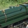
| 252 forum posts 68 photos | Hello All My wife spends a lot of time making Lino prints. It’s a process where she carves a picture into lino, puts ink on the Lino, and then prints the image onto paper. Now, before I’m allowed to move on to my next model engine project I’ve promised my wife I’ll build her a printing press The parts for the roller are shown below.
Next I tack welded everything in place.
Of course, what has happened is that the heat of the weld has distorted the central axis. Before welding it was completely true (to within < 0.01 mm across a length of 34 cm), but after welding the axis was bent at one end. Maybe with a runout of plus\minus 0.15 mm. Does anyone have any tips that I can use for MK II. I was thinking of taking things far more slowly (so the bar never gets too hot), and perhaps not turning the outer diameter until after it’s welded ? (The welding process was TIG). Any help is hugely appreciated as it took quite a while to make the parts so messing up again will be really frustrating – and delay even further the next model engine! Thanks in advance
|
| Windy | 06/12/2015 00:37:58 |
 910 forum posts 197 photos | Any way you could fasten parts mechanically i.e. lock tight adhesive, screws, rivets, press fit etc. to do away with welding and heat distortion. |
| duncan webster | 06/12/2015 01:20:46 |
| 5307 forum posts 83 photos | I would guess that the distortion is where the spindle exits the end flange, not in the main tube. I'd be tempted to address it with a hammer and try to get it a straighter, if this doesn't get it staright enough then mount it in the 4 jaw one end, fixed steady the other end, centre drill and and skim the spindle true, reverse and do the other end. If it's still not straight enough then mount between centres and skim the big diameter |
| Peter Krogh | 06/12/2015 03:29:54 |
 228 forum posts 20 photos | As a long time fabricator I can say that the rule always is weld first then machine. Any other way can be much more work!!! Pete |
| JasonB | 06/12/2015 07:35:04 |
 25215 forum posts 3105 photos 1 articles | Make the spindle from the next nominal size up and put a ctr drill hole on each end. Then when welded mount between ctrs and true up the two spindle ends as well as the main roller.
J |
| John Haine | 06/12/2015 08:21:32 |
| 5563 forum posts 322 photos | Loctite! |
| Tony Pratt 1 | 06/12/2015 08:42:05 |
| 2319 forum posts 13 photos | Weld, normalise then finish machine, or can you not make from solid? Tony |
| Nigel McBurney 1 | 06/12/2015 09:31:45 |
 1101 forum posts 3 photos | If you want it dead true,and the rollers do not look that big I would machine from solid,rough it out leave for a few days,then finish machine. In my apprenticeship days,the company made a prototype high speed continuous stationary printing,perforating and folding machine ,for the early green stripe computer paper (1961) the rollers were fabricated from tube with the ends pressed in.no loctite in those days,and welding was something that garages did,the ends were one piece ,short shaft plus the larger diameter,after pressing the whole assembly was finish machined.The perforating rollers which carried the perforating blades were machined from solid,as no deflection could be tolerated. |
| Martin Connelly | 06/12/2015 09:44:04 |
 2549 forum posts 235 photos | Have you considered using heat to correct the error, after all this is what caused it. All welds shrink as the weld pool cools from freezing point down to room temperature and no amount of mechanical restraint will stop it. The forces involved are massive. Judiciously applied heat that creates a small weld pool in the correct location will pull the part back to the desired position. If you are likely to scrap the part otherwise it is worth some time trying this. The other option is to try to relieve some of the tensions in the welds by normalising as Tony suggested but this requires taking the part to high temperature and holding it there then reducing at a controlled rate. May be hard to do correctly in a home workshop. Martin |
| Chris Evans 6 | 06/12/2015 09:48:50 |
 2156 forum posts | As above, skim in the lathe including the main roller if required. A job like this is not size critical. Make bronze bushes to suit the new spindle size or sleeve the spindle to suit roller bearings if that was your plan. I would not make it again. |
| Nick_G | 06/12/2015 09:49:56 |
 1808 forum posts 744 photos | . Could you not salvage this by finishing your intended welding. Then turn down the shafts at either end to size 'X' bringing them true. Then make sleeves with an internal bore with a close sliding fit to size 'X'. Loctite with 638 and return (if required) to desired size. Nick |
| Ajohnw | 06/12/2015 10:01:38 |
| 3631 forum posts 160 photos | Putting all of the problems together I would still use the tube and make the ends in one piece and then loctite it all together. Keeping the tube will keep the weight down compared with it all being solid. There is always a chance the the bore of tube isn't concentric to the outer diameter so I would be prepared to skim the entire thing up after assembly. You could do this after welding it all up anyway maybe even fabricating the ends. John - Edited By John W1 on 06/12/2015 10:02:17 |
| Bazyle | 06/12/2015 11:28:18 |
 6956 forum posts 229 photos | Bending back true with a vice should be possible with a little care and patience. I'm inclined to think there must be some give in the design using springs or a rubber backing on the platen that would also allow for lack of concentricity. |
| John McNamara | 06/12/2015 13:21:43 |
 1377 forum posts 133 photos | Hi David If your lathe has a fixed steady big enough to fit around the cylinder itself you could centre the cylinder with a 4 jaw chuck gripping the best of the two shafts first then turn the other down and fit a sleeve to bring it back to size. repeat for the other end if needed. You would need a dial indicator because moving one end affects the other you have to keep checking both ends until both ends are centred, it may take a few iterations to get it spot on. If the fixed steady is not big enough you could make a small cat head, in this case a steel cup with a clearance hole to fit over the end of the roller shaft drill and tap the edge of the cup at 90 degrees for 4 set screws maybe around M8 would be good. centre drill the cup. Maybe a cup depth of say 20mm and a wall and end thickness of around 10mm. The cup can be slipped over the end of the shaft and the cylinder centred on the tailstock. The roller proper can be trued up with a dial indicator. then the cylinder and the shaft can be trued (Except for the bit under the small cup maybe 20mm). to finish the last bit remove the cup and set up the fixed steady on the now true shaft and finish off the last 20mm. Repeat for the other end. Because of the stresses set up by the welds the shafts may move after part of the weld is removed. To be certain the process above maybe better done in two passes. leaving a few thousandths for the second pass. When you weld a piece of metal the white hot pool of metal expands and is then rapidly cooled by the surrounding metal creating an area of tension. the tension can be equal to the tensile strength of the metal itself 40 to 100,000 PSI, even a slam weld can bend a thick shaft or plate. Regards
|
| David Cambridge | 06/12/2015 13:27:12 |
| 252 forum posts 68 photos | I think you’ve all saved the day! Thank you for all the very helpful and detailed replies. The lesson I’ve learnt for next time is weld then machine, not the other way round (i.e. ‘when welded mount between ctrs and true up’ and ‘the rule always is weld first then machine. The plans call for the roller to go in take up bearings and they come in sizes of 20mm, 17mm , and 15mm. The plans also call for a 20mm shaft, and so I didn’t want to turn the shaft down to the next size of 17mm in case if flexes too much in use. Hence I’d originally dismissed that idea. Anyway, after that some of you then subsequently suggested that I try and salvage by turning down and that made me rethink. Next I discovered that I can get imperial bearings that are 19.05mm – which should be fine. I really wasn’t excited about making it again! After a quick spin in the lathe it’s looking great! David Edited By David Cambridge on 06/12/2015 13:27:30 Edited By David Cambridge on 06/12/2015 13:28:54 |
| John McNamara | 06/12/2015 13:50:27 |
1377 forum posts 133 photos | Slam weld? typo! I should have said small weld. |
| Boiler Bri | 06/12/2015 19:53:59 |
 856 forum posts 212 photos |
I have some 2" en8 if you want to make them from solid. Spare and free to a good home if you pay the postage. Brian |
| Chris Evans 6 | 06/12/2015 20:40:31 |
2156 forum posts | David, I think you will find 19mm bearings cheaper than 3/4". I find imperial size stuff is getting pricey now it is not used often. |
| David Cambridge | 06/12/2015 22:03:20 |
| 252 forum posts 68 photos | Boiler Bri – that’s very kind of you, thank you, but I think I’m now in the clear. (I think making them from solid is a good idea, but it would carry too much of a weight burden) Chris Evans – thanks, but I managed to find some at a reasonable cost on eBay. |
| Ian S C | 07/12/2015 09:54:30 |
 7468 forum posts 230 photos | Sometimes a shaft like yours can be straightened just by grinding back the weld opposite the bend a bit then rewelding, it's a bit hit and miss, but worth a go. Not long after I bought my bandsaw, I needed to cut some long bits of steel, so I made a stand with a roller on the top. It has no welds, in the ends of the roller (2" dia) are the bearings, and a shaft goes through this with an inch out each end. There is one weld because the bit of pipe I had was not long enough, so I joined two bits, and skimmed it off in the lathe. Ian S C Edited By Ian S C on 07/12/2015 10:01:29 |


Please login to post a reply.
Magazine Locator
Want the latest issue of Model Engineer or Model Engineers' Workshop? Use our magazine locator links to find your nearest stockist!
Sign up to our Newsletter
Sign up to our newsletter and get a free digital issue.
You can unsubscribe at anytime. View our privacy policy at www.mortons.co.uk/privacy
Latest Forum Posts
- hemingway ball turner
04/07/2025 14:40:26 - *Oct 2023: FORUM MIGRATION TIMELINE*
05/10/2023 07:57:11 - Making ER11 collet chuck
05/10/2023 07:56:24 - What did you do today? 2023
05/10/2023 07:25:01 - Orrery
05/10/2023 06:00:41 - Wera hand-tools
05/10/2023 05:47:07 - New member
05/10/2023 04:40:11 - Problems with external pot on at1 vfd
05/10/2023 00:06:32 - Drain plug
04/10/2023 23:36:17 - digi phase converter for 10 machines.....
04/10/2023 23:13:48 - More Latest Posts...
- View All Topics
Support Our Partners


Shopping Partners
Subscription Offer

Latest "For Sale" Ads
- Reeves** - Rebuilt Royal Scot by Martin Evans
by John Broughton
£300.00 - BRITANNIA 5" GAUGE James Perrier
by Jon Seabright 1
£2,500.00 - Drill Grinder - for restoration
by Nigel Graham 2
£0.00 - WARCO WM18 MILLING MACHINE
by Alex Chudley
£1,200.00 - MYFORD SUPER 7 LATHE
by Alex Chudley
£2,000.00 - More "For Sale" Ads...
Latest "Wanted" Ads
- D1-3 backplate
by Michael Horley
Price Not Specified - fixed steady for a Colchester bantam mark1 800
by George Jervis
Price Not Specified - lbsc pansy
by JACK SIDEBOTHAM
Price Not Specified - Pratt Burnerd multifit chuck key.
by Tim Riome
Price Not Specified - BANDSAW BLADE WELDER
by HUGH
Price Not Specified - More "Wanted" Ads...
Get In Touch!
Do you want to contact the Model Engineer and Model Engineers' Workshop team?
You can contact us by phone, mail or email about the magazines including becoming a contributor, submitting reader's letters or making queries about articles. You can also get in touch about this website, advertising or other general issues.
Click THIS LINK for full contact details.
For subscription issues please see THIS LINK.
Digital Back Issues


Donate

 Register
 Log-in
Model Engineer Magazine
- Percival Marshall
- M.E. History
- LittleLEC
- M.E. Clock

ME Workshop
- An Adcock
- & Shipley
- Horizontal
- Mill

Subscribe Now
- Great savings
- Delivered to your door

Pre-order your copy!
- Delivered to your doorstep!
- Free UK delivery!
All Forum Topics > Beginners questions > Welding Help for Building a Printing Press