Forum sponsored by:

Todays update from Bodgers Lodge
| John Stevenson | 28/12/2015 20:58:24 |
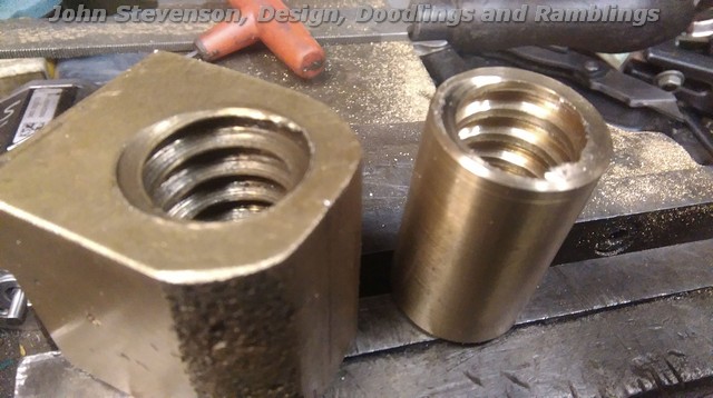
 5068 forum posts 3 photos | Today's escapade was to make a new cross slide nut for an Edgwick lathe. The old screw was quite good but the nut was toast.
Internal threads are like razors and it will soon rip out what's left. Photographed this from the wrong side really as the bottom is complex with dowels and tenons machined in, plus it's a biggish lump of bronze so being idle as it holiday time made an insert out of a bit of round bronze bar.
Thread is 7/8" x 5 tpi LH Acme.
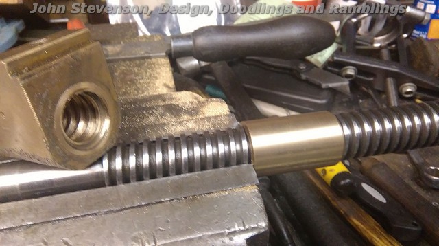
So setup the lathe for imperial threading and belt a couple of nuts off, one to fit and one as a spare for the guy as it takes longer to setup than screwcut the new nut.
Machine a plain diameter dummy shaft up that is a push fit in the worn nut, setup in the four jaw with dummy shaft running true and bore out. Press fit and loctite the new nut in.
Knock off and go feed the dog. |
| David Clark 1 | 29/12/2015 14:04:06 |
 3357 forum posts 112 photos 10 articles | Don't forget to put the bins out. |
| mark costello 1 | 29/12/2015 14:37:13 |
 800 forum posts 16 photos | Have to do the same exact job when I can afford a roundtoit. |
| John Stevenson | 29/12/2015 15:08:44 |
5068 forum posts 3 photos | Posted by David Clark 1 on 29/12/2015 14:04:06:
Don't forget to put the bins out. .
.
Thursday. |
| John Stevenson | 31/12/2015 12:02:14 |
5068 forum posts 3 photos | David, I remembered the bins. |
| John Stevenson | 31/12/2015 21:54:29 |
5068 forum posts 3 photos | Now anyone of a delicate disposition, that's anyone who feels the Teletubbies are violent do not read the following.
Over the last few days I have been doing shop maintenance on machines etc as it's one of the few times per year I can catch up.
Silly things like making sure all the nuts and bolts on the mill share the same 3/4" A/F spanner instead of hunting different tools out. Same for the lathe chucks which in my case are 'A' series that bolt on. I much prefer these to camlocks as they cannot come loose on heavy interrupted cuts like laser cut plates. 8 different chucks means 32 nuts and over the time having been sourced from different suppliers has again finished up with different spanner sizes.
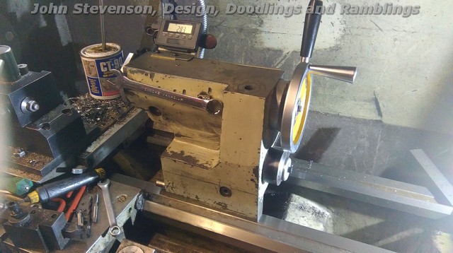
Anyway today I started to address the tailstock problem on the TOS lathe. It's my belief that only the British can design a decent tailstock. The Chinese / Taiwanese don't stand a cat in hells chance and TOS / Eastern European are only second place behind them. The only thing TOS have going for them is, if a 10 lb casting will do, they have to use 25 lbs.
So the problems.
Three things wrong with it. [1] Usual ejects the taper before getting back to zero which is just sorting the screw out. [2] Locking for the tailstock. From new this was just a long threaded rod into the bottom clamp and a nut and washer on the top which means using / finding a spanner every time and it wasn't as easy as fitting a simple handle as it needs about two full turns to clamp up because of the clamp design.
The system shown was one I did many years ago and the idea pinched off Honda as that is how they operate the clutch on the C50 / C90 step thru's although they use ball bearings in between. It gives the facility to lift the rod a long way with a short travel. It's worked well for years but never been pleased with it's looks and it will be in the way when I continue to modify this tailstock and fit a lever and screw feed.
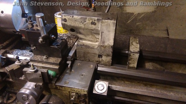
[3] Biggest drawback is just that. This thing is massive and the base is over long with the problem you start off with the barrel half way out to reach the work, not made any better since fitting a cross slide DRO. Now this is where it gets messy. Measured up and Deb's Bantam has a 6 1/2" long tailstock, my Chinese lathe which is bigger than the TOS also has a 6 1/2" long tailstock. If this one is cut off to make it flat fronted and get rid of the overhang it would still be 7" long. Stripped down, no spindle, clamps etc, just a bare casting this puppy weights 33Kg !!
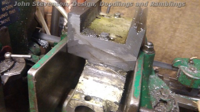
So stick it on the power saw and cut from both sides because of the blade angle and then onto the mill to clean up.
However the cut was so good and it's only a casting I just cleaned it up with the angle grinder and a flap wheel. It will need a repaint anyway.
Offer it back up and jobs a good un.
Gained an extra 48mm of space and a nice lump of cast iron to boot.
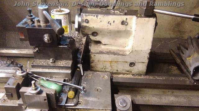
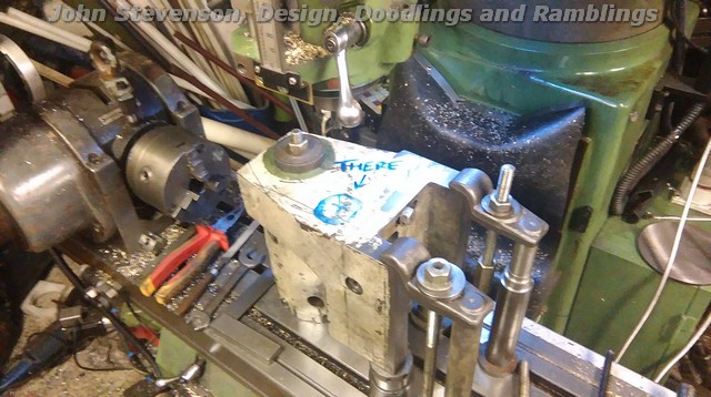
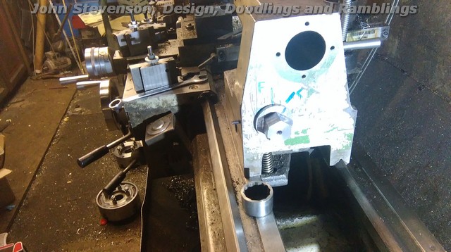
Next up is problem [2], so stick it on the mill by it's nose and clamp down. Accurately mark out where the hole for the clamp stud is and start drilling and boring out.
Bore out to 50mm diameter and 50mm deep because it sounds nice numbers, and remove.
That's as far as I have got tonight, now took some measurements and retreated into the scribble pit ™ © ® to work out how to get an eccentric locking system fitted into the hole.
Edited By John Stevenson on 01/01/2016 14:10:28 |
| John Stevenson | 02/01/2016 21:51:26 |
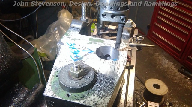
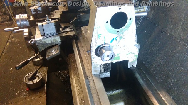
5068 forum posts 3 photos | Got sidetracked yesterday on something else so picked this up today but didn't get a chance to do any scribbling so in the best laid plans, weld it where it touches. First job, new shorter pull stud and link for the top and square nut for the bottom. The bottom nut fits in a slotted recess as it can't turn, that is the adjustment.
Eccentric was made out of a lump of scrapbinium ™ and turned to fit the hole, groove in for a retaining screw, 10mm hardened dowel pin fitted 10mm on the eccentric and a hexagon put on the outboard end but more on this after the other couple of pics.
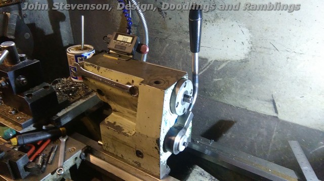
When the line on the hexagon is lined with the vertical line 'F' then it's free to slide, rotate it about 30 degrees with a spanner and it's locked, tried driving it back with the saddle under power but the clutch on the feed slips so that's me one happy bunny.
That is a cut down 11/16 Whit socket on the bed that's fit the hexagon, chose that size as I have three of them and won't miss one.
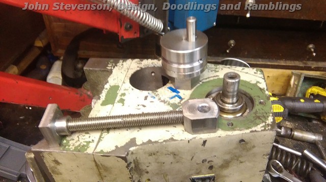
Because this has genuinely all been done with no drawings or sketches I wasn't sure where the handle would fit and at what angle it would come out if I fitted it directly to the eccentric. So the idea is to shrink this cut down socket into a thick walled sleeve and I have 12 positions now to get it somewhere near and if I do cock up then it's a simple job to turn the sleeve off and start again.
Socket fitted to see how much room I have without fouling the handwheel [ not fitted at this point ].
So tomorrow, sleeve to do, handle to do, refit the iGauging DRO and a stop sleeve on the front so it hits the saddle before anything else does. That will make it a far nicer machine to use. At a later day I plan to follow on with a lever / screw feed tailstock.
|
| John Stevenson | 03/01/2016 23:30:40 |
5068 forum posts 3 photos | Last lap.
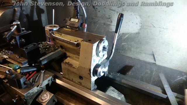
DRO fitted, stop on the front fitted so it doesn't whack the cross slide DRO and handle made and fitted. This is the handle in the unlocked position, tailstock hand wheel removed for ease of fitting and clarity.
Handle in the locked position, no spring, dead positive in operation.
All finished working. Two very strong magnets fitted to the side to hold the toolpost and chuck spanner. Need a plug to fit in the original clamp hole and drilled 5.8mm to hold the allen key for the quick change tool-posts.
Very pleased with this mod, should save some time in all the winding in and out but just makes it so much nicer to use. |
| John Stevenson | 15/01/2016 23:25:37 |
5068 forum posts 3 photos | Thought I'd post this one just for laughs.
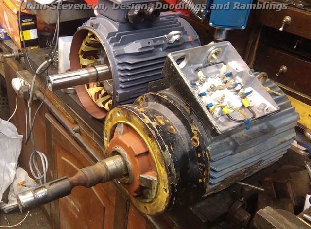
So Thursday morning get a pump in for repair and it was in a bit of a state. It supposedly pumps some sort of chemical or more than likely corrosive but it has a steel shaft ?
It has three impellers, one keyway is at 180 degrees, out of sight and behind the last impeller is a seal, that's the bit that's worn away, so guess it's leaking a tad ?
So the instructions are, "Make the new motor look like the old motor but without the wear and do it in stainless 316, No rush, few days as they have fitted the standby pump."
So order a lump of 10" steel 4.5" thick and it will be here Tuesday, Stainless will land Friday morning. Nice little earner without breaking a sweat.
So this morning at five past seven gets woke up in me pit with the news that the standby pump burnt out in the night and this one is now desperate and to get something out the door for late dinner. As the old pump is electrically sound, decided to repair this and still do the new one for later when the steel comes in.
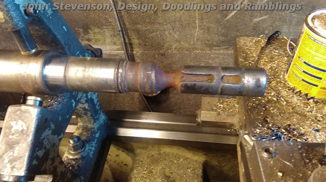
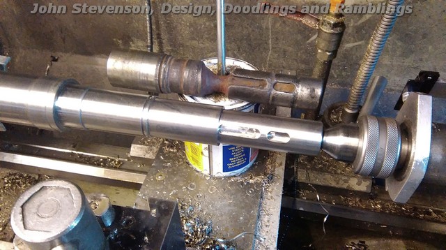
So belt it in the lathe, chop the bad bit off. Drill, bore and ream a 50mm hole up the spout, shrink and press a big lump of stainless in, weld it where it touches and turn to finish.
Jobs a good un and can now try and get back to working out why me hobber is playing up, or more to the point throw all the old control gear away and fit some new updated gear in it's place. |
| Peter Krogh | 16/01/2016 00:08:59 |
 228 forum posts 20 photos | I love your posts John! Keep 'em coming... Pete |
| Hopper | 16/01/2016 02:50:57 |
 7881 forum posts 397 photos | Nice work once again! What did they ever do before they had you to pull them out of the fertilizer? |
| Neil Wyatt | 16/01/2016 10:34:47 |
 19226 forum posts 749 photos 86 articles | from the look of the old shaft, I reckon you've been stirring your coffee with it.
|
| mechman48 | 16/01/2016 12:15:08 |
 2947 forum posts 468 photos | Nice job. Did your welding not damage the rotor in any way, alter the magnetism etc. just curious as not into electrickery at that level ? George. |
| John Stevenson | 16/01/2016 12:18:30 |
5068 forum posts 3 photos | Neil, No way I use titanium tea spoons
I would have loved to keep the old shaft and mount it on the wall but they asked for it back to show the customer. Now waiting to see if they cancel the new motor job and just have the standby rewound If they do I will be the proud owner of a lump of steel 10" diameter and 4 1/2" thick that was destined for a new end plate - paid for of course.
{EDIT}
George, There is no magnetism in a rotor, it's made up of iron laminations with cast alloy in between that acts as the winding. You can get these absolutely glowing and not cause any problems. There needs to be a magnetic path for the induced current from the stator and one thing you cannot do is replace the whole shaft with a 300 series non magnetic stainless shaft thru the rotor. If you do it just runs at low speed and gets hot in a very short time. Stainless shafts have to be either stubbed or turned down and coated with stainless weld and turned back to size again.
Majority of pumps shafts that are not plain steel are stubbed. Edited By John Stevenson on 16/01/2016 12:24:27 |
| Circlip | 16/01/2016 12:32:32 |
| 1723 forum posts | 'Spose you realize just how much you're screwing up the Chineze economy? They are closing motor manufacturing factories left right and Thursdays thanks to your bodging?
Regards Ian. "Drill and ream a 50mm hole" is that dia. or depth? What's shaft diameter?
Edited By Circlip on 16/01/2016 12:36:15 Edited By Circlip on 16/01/2016 12:36:33 |
| John Stevenson | 16/01/2016 12:47:51 |
5068 forum posts 3 photos | Sorry, bragging rights, it should read 40mm diameter. Hole goes up the spout 120mm or 5" for support. Shaft then descends to 38 where the seal fits, then 35 where the impellers fit. |
| Harry Wilkes | 16/01/2016 15:36:27 |
 1613 forum posts 72 photos | John your photos of the pump shaft takes me back I spent 27 years in the metal finishing trade so sights like that were not uncommon, nice work ! H |
| mechman48 | 16/01/2016 18:33:17 |
2947 forum posts 468 photos | Thanks for the info' on the electrickery aspect John; must put that into the old memory banks, if I can remember what & where they are... George. |
| Allan B | 01/04/2016 22:38:57 |
 133 forum posts 23 photos | Had some time to kill so I have just read this thread from start to end :D
got to say some very interesting ways of working around a problem, looking forward to reading more |
| JimmieS | 01/04/2016 22:44:30 |
| 310 forum posts 1 photos | Any more insights into processes unknown to we of little knowledge from the master of ingenuity? Jim |

Please login to post a reply.
Magazine Locator
Want the latest issue of Model Engineer or Model Engineers' Workshop? Use our magazine locator links to find your nearest stockist!
Sign up to our Newsletter
Sign up to our newsletter and get a free digital issue.
You can unsubscribe at anytime. View our privacy policy at www.mortons.co.uk/privacy
Latest Forum Posts
- *Oct 2023: FORUM MIGRATION TIMELINE*
05/10/2023 07:57:11 - Making ER11 collet chuck
05/10/2023 07:56:24 - What did you do today? 2023
05/10/2023 07:25:01 - Orrery
05/10/2023 06:00:41 - Wera hand-tools
05/10/2023 05:47:07 - New member
05/10/2023 04:40:11 - Problems with external pot on at1 vfd
05/10/2023 00:06:32 - Drain plug
04/10/2023 23:36:17 - digi phase converter for 10 machines.....
04/10/2023 23:13:48 - Winter Storage Of Locomotives
04/10/2023 21:02:11 - More Latest Posts...
- View All Topics
Support Our Partners


Shopping Partners
Subscription Offer

Latest "For Sale" Ads
- Reeves** - Rebuilt Royal Scot by Martin Evans
by John Broughton
£300.00 - BRITANNIA 5" GAUGE James Perrier
by Jon Seabright 1
£2,500.00 - Drill Grinder - for restoration
by Nigel Graham 2
£0.00 - WARCO WM18 MILLING MACHINE
by Alex Chudley
£1,200.00 - MYFORD SUPER 7 LATHE
by Alex Chudley
£2,000.00 - More "For Sale" Ads...
Latest "Wanted" Ads
- D1-3 backplate
by Michael Horley
Price Not Specified - fixed steady for a Colchester bantam mark1 800
by George Jervis
Price Not Specified - lbsc pansy
by JACK SIDEBOTHAM
Price Not Specified - Pratt Burnerd multifit chuck key.
by Tim Riome
Price Not Specified - BANDSAW BLADE WELDER
by HUGH
Price Not Specified - More "Wanted" Ads...
Get In Touch!
Do you want to contact the Model Engineer and Model Engineers' Workshop team?
You can contact us by phone, mail or email about the magazines including becoming a contributor, submitting reader's letters or making queries about articles. You can also get in touch about this website, advertising or other general issues.
Click THIS LINK for full contact details.
For subscription issues please see THIS LINK.
Digital Back Issues


Donate

 Register
 Log-in
Model Engineer Magazine
- Percival Marshall
- M.E. History
- LittleLEC
- M.E. Clock

ME Workshop
- An Adcock
- & Shipley
- Horizontal
- Mill

Subscribe Now
- Great savings
- Delivered to your door

Pre-order your copy!
- Delivered to your doorstep!
- Free UK delivery!
All Forum Topics > Workshop Techniques > Todays update from Bodgers Lodge