Forum sponsored by:

Bench grinder improvement mod.
| Rik Shaw | 23/05/2014 19:03:33 |
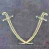 1494 forum posts 403 photos | I have several bench grinders all of an eastern persuasion and all have the same design of grinding spindle nose as shown in pic1.
The problem here is the miniscule "flange" arrowed at "2" which is supposed to help stop the wheel from wobbling from side to side.
I bought yet another grinder from the boot last weekend for a couple of quid and on trying it out when I got back home I could see why they wanted to get rid of it. One of the wheels was running so far out it was dangerous to run it up to speed, so I have set to and come up with a mod which corrects this problem on these cheap Chinese machines. My corrective flange now relies on diameter "1" for eliminating sideways wobble on the wheel. The flange is bored out to be an accurate fit on diameter "1" and flange edge "2" now becomes a simple stop. The shoulder which goes up against this "flange" can be seen inside the bore on one of the other pics.
You can see the results here:
Rik Edited By Rik Shaw on 23/05/2014 19:05:59 |
| Tony Payn | 30/05/2014 21:34:47 |
| 10 forum posts | Hello Rik That's a neat way to rescue a condemned grinder and is an improvement that ought to come as standard. Thanks for sharing it! Tony |
| derek hall 1 | 07/10/2018 08:05:58 |
| 322 forum posts | Hi all, sorry to resurrect an old thread but... The original design of locating wheels as seen on many bench grinders, including my new 8 inch arc Euro trade Allwin is a poor design. Does the modified design improve things as shown by Rik in the original post I.e. side to side wobble? In passing how come so many grinding wheel have holes that are non standard. Does this mean that you have to buy or make a bush to suit and what sort of "fit" to wheel and shaft should we be looking for? Finally! Should all new grinders/wheels to dressed before use and for the standard wheels is a single point diamond suitable? Regards to all Del |
| Mike Poole | 07/10/2018 10:45:14 |
 3676 forum posts 82 photos | Many wheels have a standard 1 1/4” or 31.75mm hole and are bushed to suit grinder shaft. The shoulder on the shaft is an inadequate location especially for the typical pressed flanges. I make a new inner flange with a 31.75mm boss for the wheel, make the hole for the shaft a push fit and it should keep the flange running true. You will probably need a new wheel as they are often made with the hole to fit the shaft. The wheels will need dressing to run true and I will do a one time dress to the sides to true them which I feel a 25mm wheel could take without causing a problem. I do not recommend this from the position of being an expert so do it at your own risk. A smooth running and true wheel is a pleasure to use. Mike |
| DMB | 07/10/2018 11:29:15 |
| 1585 forum posts 1 photos | Cromwell Tools sell sets of plastic bushes in diff. dias., especially for mounting grinding wheels of various bores. No fin. Interest, just satisfied customer. I once purchased a white cup wheel from them and a set of bushes. |
| mechman48 | 07/10/2018 16:52:38 |
 2947 forum posts 468 photos | http://youtu.be/n51JPRkj85I … |
| John Baron | 07/10/2018 17:36:44 |
 520 forum posts 194 photos | Hi Guys, That tiny lip becomes an issue with the cheap nasty monkey metal flanges that seem to get supplied with most grinders nowadays. A good close fitting washer works wonders, extending the bore of the washer is even better ! Better still is facing the washer square actually on the grinder shaft. Don't forget to use blotters on each side of the wheel.
|
| Neil Wyatt | 07/10/2018 19:53:34 |
 19226 forum posts 749 photos 86 articles | 3D printing seems an obvious route for making custom bushings. Whatever you do, don't forget the card washers! Neil |
| Robert Dodds | 07/10/2018 20:48:18 |
| 324 forum posts 63 photos | No mention has been made so far about the need for both flanges to be similarly recessed away from the bore so as to put even clamping forces on the wheel. There are some clear illustrations in a HSE handbook on the subject that's free to download at (http://www.hse.gov.uk/pUbns/priced/hsg17.pdf). Bob D |
| Pete Rimmer | 07/10/2018 22:31:49 |
| 1486 forum posts 105 photos | I've done that to all of my grinders. You get a nice true-running wheel and a wide choice of grits and hardnesses. |
| Michael Horner | 08/10/2018 07:36:51 |
| 229 forum posts 63 photos | For this, I added larger flanges, using adhesive, to the grinders spindles and turned these true with the grinder running whilst fixed to the lathes bed. The advantage of this, together with the accurately made adaptors, is that the wheels can be interchanged and only need truing up the first time they are run. The above is from Harold Halls website of how he dealt with the issue. Cheers Michael |
| Rik Shaw | 08/10/2018 10:03:49 |
1494 forum posts 403 photos | "comes up with 'video not available' … ?" Thanks for pointing that out George, it looks like YouTube have "lost" my vid. I have checked back on some of my other movie links associated with posts here and they all seem intact . As the "before and after" can no longer be viewed I can confirm that the mod worked well and the wobbly wheel was made to run true. Rik |


Please login to post a reply.
Magazine Locator
Want the latest issue of Model Engineer or Model Engineers' Workshop? Use our magazine locator links to find your nearest stockist!
Sign up to our Newsletter
Sign up to our newsletter and get a free digital issue.
You can unsubscribe at anytime. View our privacy policy at www.mortons.co.uk/privacy
Latest Forum Posts
- *Oct 2023: FORUM MIGRATION TIMELINE*
05/10/2023 07:57:11 - Making ER11 collet chuck
05/10/2023 07:56:24 - What did you do today? 2023
05/10/2023 07:25:01 - Orrery
05/10/2023 06:00:41 - Wera hand-tools
05/10/2023 05:47:07 - New member
05/10/2023 04:40:11 - Problems with external pot on at1 vfd
05/10/2023 00:06:32 - Drain plug
04/10/2023 23:36:17 - digi phase converter for 10 machines.....
04/10/2023 23:13:48 - Winter Storage Of Locomotives
04/10/2023 21:02:11 - More Latest Posts...
- View All Topics
Support Our Partners


Shopping Partners
Subscription Offer

Latest "For Sale" Ads
- Reeves** - Rebuilt Royal Scot by Martin Evans
by John Broughton
£300.00 - BRITANNIA 5" GAUGE James Perrier
by Jon Seabright 1
£2,500.00 - Drill Grinder - for restoration
by Nigel Graham 2
£0.00 - WARCO WM18 MILLING MACHINE
by Alex Chudley
£1,200.00 - MYFORD SUPER 7 LATHE
by Alex Chudley
£2,000.00 - More "For Sale" Ads...
Latest "Wanted" Ads
- D1-3 backplate
by Michael Horley
Price Not Specified - fixed steady for a Colchester bantam mark1 800
by George Jervis
Price Not Specified - lbsc pansy
by JACK SIDEBOTHAM
Price Not Specified - Pratt Burnerd multifit chuck key.
by Tim Riome
Price Not Specified - BANDSAW BLADE WELDER
by HUGH
Price Not Specified - More "Wanted" Ads...
Get In Touch!
Do you want to contact the Model Engineer and Model Engineers' Workshop team?
You can contact us by phone, mail or email about the magazines including becoming a contributor, submitting reader's letters or making queries about articles. You can also get in touch about this website, advertising or other general issues.
Click THIS LINK for full contact details.
For subscription issues please see THIS LINK.
Digital Back Issues


Donate

 Register
 Log-in
Model Engineer Magazine
- Percival Marshall
- M.E. History
- LittleLEC
- M.E. Clock

ME Workshop
- An Adcock
- & Shipley
- Horizontal
- Mill

Subscribe Now
- Great savings
- Delivered to your door

Pre-order your copy!
- Delivered to your doorstep!
- Free UK delivery!
All Forum Topics > Manual machine tools > Bench grinder improvement mod.