
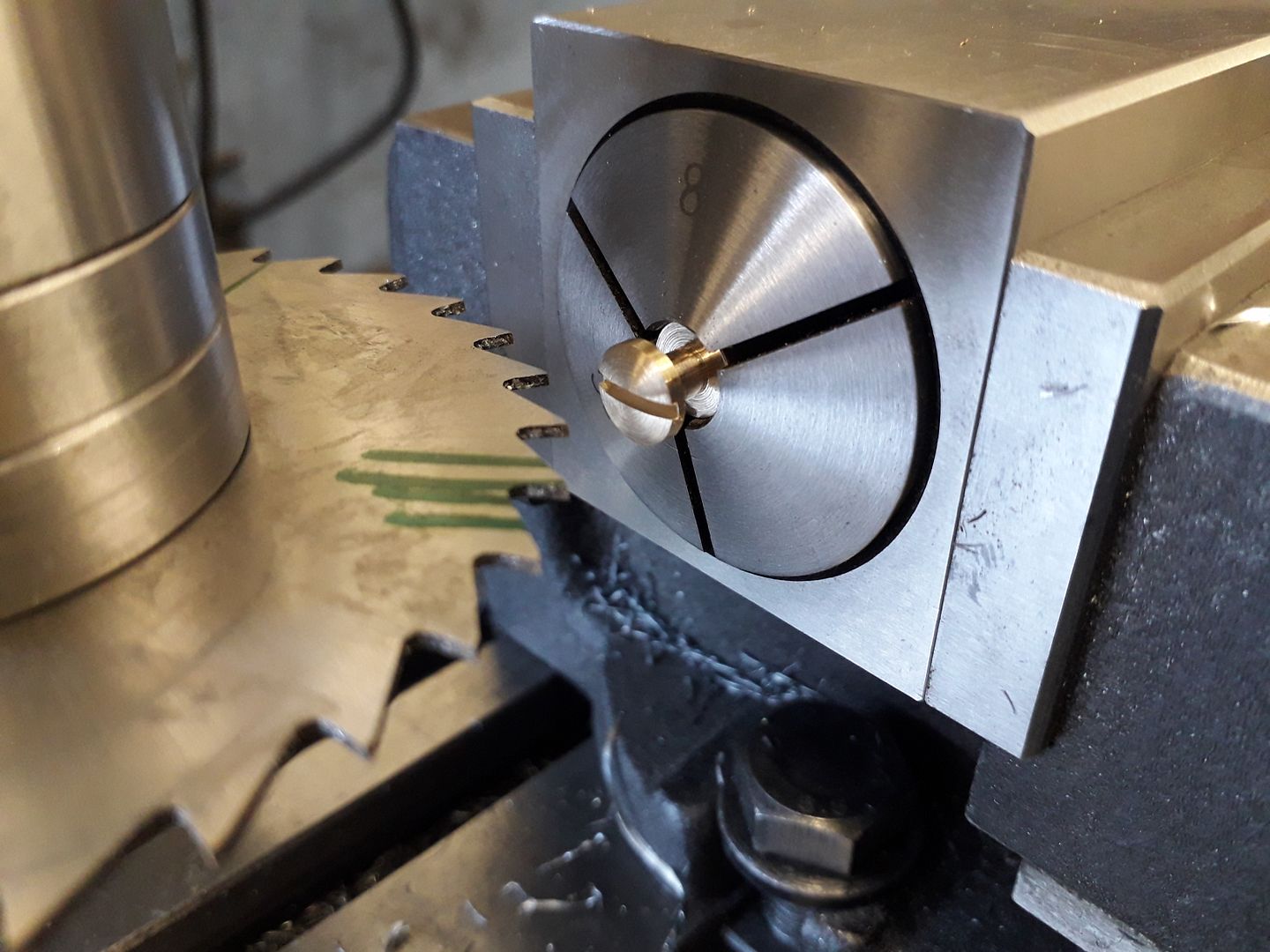
Cutting a slot in a screwhead
8mm screw, centering the circular saw to the head.
| Clive Hartland | 29/07/2022 19:48:34 |
 2929 forum posts 41 photos | I am slotting some bronze screwheads for a friend. He modifies theodolites for non magnetic standards. All ferrous screws changed for bronze. He makes the screws and they need slotting. I have a 2mm saw mounted on the mill vertical drive and screws held in the vice in a collet in a square johnson block. What is best method of ensuring the slot is central,in the screw head. I have a DRO fitted to the mill and readout system. Hard to get a measuring tool into the setup to check. Any ideas please. |
| JasonB | 29/07/2022 19:55:45 |
 25215 forum posts 3105 photos 1 articles | I tend to turn the saw back and forth by hand while lowering it and touch it onto the top edge of the screw head, you can do it by feel or with a fag paper. Zero the DRO at this point. Now feed down by half the saw thickness plus half the screw head dia and you should be on ctr line |
| DC31k | 29/07/2022 20:01:34 |
| 1186 forum posts 11 photos | Is there any advantage or ease to be gained by touching off on the top surface of your Johnson? Maybe a bright light could substitute if your fags are now paperless. |
| Clive Brown 1 | 29/07/2022 20:25:44 |
| 1050 forum posts 56 photos | I'd try putting into the collet a throwaway piece of material same diameter the screw thread.. Cut a slot and then re-adjust the position by trial and error until it looks right. Then cut the actual screws; but I haven't got a DRO! |
| Ian P | 29/07/2022 20:41:17 |
 2747 forum posts 123 photos | I find its a very trial and error process. I sometimes true up arbor faces and spigot diameters in the lathe and without removing the arbor from the lathe, fit the blade and still get runout at the saw teeth. I could probably reduce the blade wobble by having a large diameter arbor that only leaves enough of the saw teeth exposed for the depth I intend to cut. I find that with, say a 1mm wide x 75mm dia sawblade with a 38 diameter arbour if there is any wobble the slot position partly depends on which part of the blade circumference make first contact and makes a channel for the rest of the blade teeth to follow. Ian P
|
| Emgee | 29/07/2022 20:51:39 |
| 2610 forum posts 312 photos | On the last gudgeon pin remover tool I made, using an arbor mounted 2.75mm diam saw in a vertical spindle, I bought the slowly rotating 0.50mm thick blade down to touch off the top of the 4mm diameter part held in a horizontally fitted indexing/dividing head, set the Z axis to zero, moved off in the X direction until clear then dropped the blade to below the part, raised the blade to touch off the part and read the Z readout, moved off the part again in the X axis and raised the head 1/2 the recorded distance. Set the spindle revs to 300 and using the X axis moved the blade into the work by the 10mm required with a feedrate of 30mm/min. Using this method evens out any runout on the blade and gives a spot on centre cut. Emgee Ian P beat me to it. Edited By Emgee on 29/07/2022 20:54:12
Edited By Emgee on 29/07/2022 21:04:51 |
| John ATTLEE | 29/07/2022 21:20:15 |
| 49 forum posts | I would normally do exactly as Emgee has done with DRO. I find DRO on the Z axis very useful. However, I have done it by taking the blade out, touching off the appropriate surface of the arbor. I then raise the table by the appropriate amount (half the blade dia + half the head or a useful bit of round HSS bar 3/8 dia). Seems to work fine even with me!
John |
| old mart | 29/07/2022 21:39:02 |
| 4655 forum posts 304 photos | I would use the Clive Brown method. |
| Clive Hartland | 29/07/2022 22:04:50 |
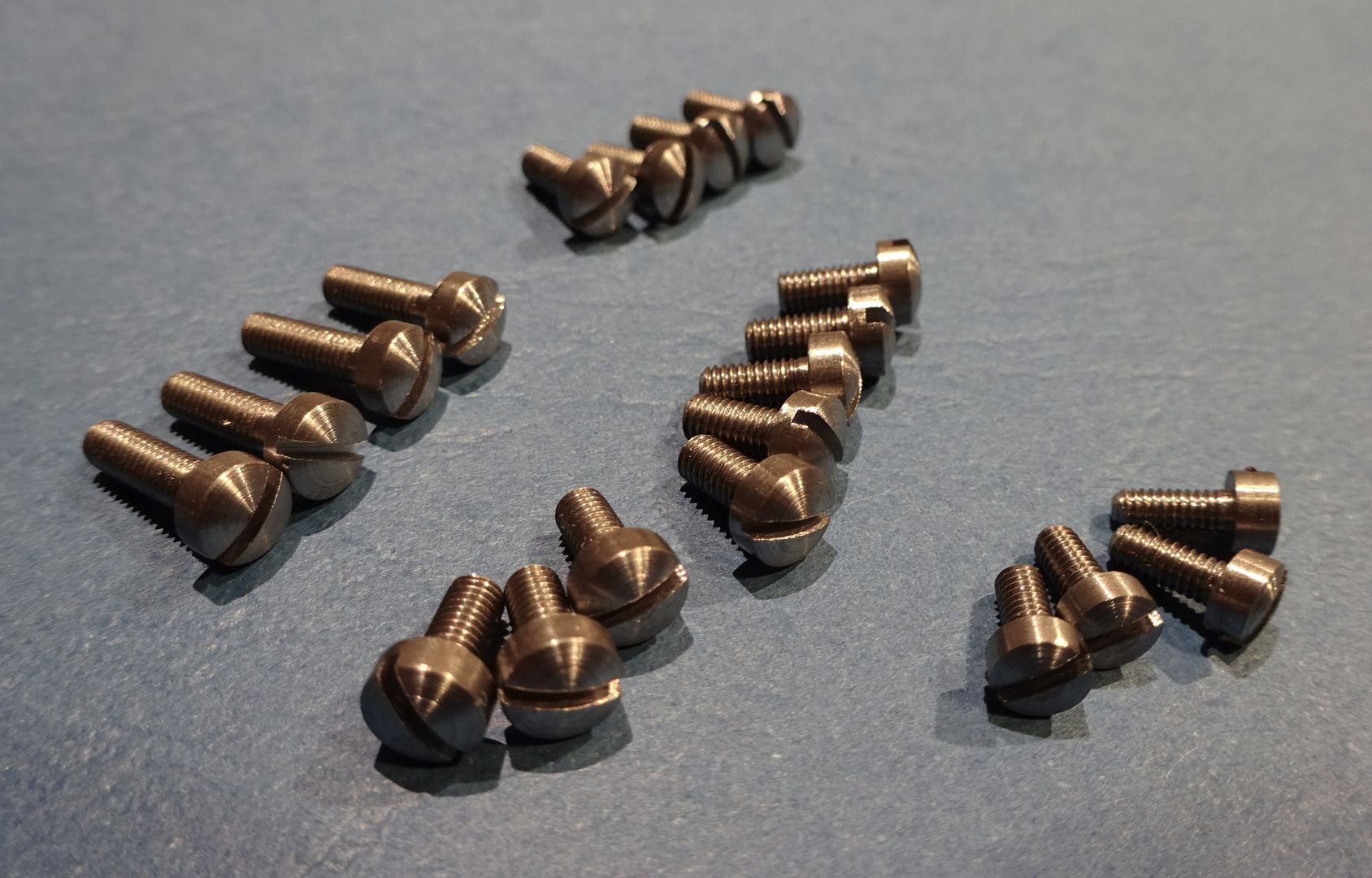
2929 forum posts 41 photos | Thanks Gentlemen, the sacrificial pin of thread diameter seems the way to go. I have over a 100 to do! As he is a long time good friend I cannot ask him to pay. Clive |
| Clive Foster | 29/07/2022 23:30:24 |
| 3630 forum posts 128 photos | For this sort of job I prefer known error methods where a suitable test cut is made deliberately offset from the desired position and the actual offset derived by measurement and calculation allowing things to be adjusted to place the cut correctly on the actual workpiece. Especially so if a DRO system is fitted as it makes compensating for the deliberate error in the test cut much easier than when using conventional methods. For this job I'd make a dummy cheesehead "screw" and slice part of the head off leaving a D shape. The position of the flat side of the D can be measured to appropriate accuracy hence establishing the position of the lower side of the screw slot produced at that vertical position of the slitting saw. Given the diameter of the dummy "screw" head and measuring the depth of the D the offset needed to put the bottom of the slot to be cut in the proper screws exactly half the width of the screw slot below the collet centre line can be calculated. I tend to break out the CAD system and accurately draw the proper screw head along with the D shape test dummy. Clive |
| John Reese | 30/07/2022 02:35:34 |
 1071 forum posts | JasonB stated the ideal method. It also works for setting a Woodruff cutter or gear cutter on center. |
| JasonB | 30/07/2022 07:14:42 |
25215 forum posts 3105 photos 1 articles | It works for me as would the touching top & bottom then using the half function. DC31K's method of setting to the top of the collet block would also be easy and then just lower by half block height + half saw thickness.
|
| AdrianR | 30/07/2022 07:22:54 |
| 613 forum posts 39 photos | I use a DTI, zero it on the part then adjust the cutter height using the DTI. Add 1/2 the thickness of the cutter and part you are at the centre. If you revolve the saw you can compensate for the wobble too. |
| Martin Kyte | 30/07/2022 08:29:27 |
 3445 forum posts 62 photos | Or leave a saw width witness on the head of the screw and adjust the saw by eye using a loupe. Personally I cut screw slots with a knife file positioning the file with my thumbnail. as the cut progresses a small sideways force is sufficient to correct any positional error. This method also produces a slot with tapered sides so the driver fits correctly. regards Martin |
| Clive Foster | 30/07/2022 08:38:01 |
| 3630 forum posts 128 photos | Touch off methods fundamentally assume that there are no infelicities in workpiece mounting, tool grind or cutting behaviour that may affect the relationship between touch position and the edges of the actual cut. It is of course a given that the tool and work be sufficiently stiff not to deflect when the (gentle) touch is made. Like many folk I find the "just tears cigarette paper "or "drag a feeler gauge out of the gap" methods give a better feel for precise touch off than simply bringing the tool down onto workpiece or reference for those jobs that have to be so right that even Inspector Meticulous may smile, briefly. Nice thing about the known error method is that all infelicities are eliminated because measurements and settings are referenced to an actual cut. Its also generally quicker. Eye up cutter for a suitable sweep across a sacrificial component or set up dummy to make the D. If you have one set DRO to zero, use a different memory if need be so you don't loose important datums. Measure depth of D and height of flat above table. (Verify that the results are consistent. I'm a great fan of paired check measurements as the habit has saved me significant time when a set-up wasn't what I thought it ought to have been.) Move cutter so as to bring it to the calculated correct position. Make a second check cut on another sacrificial or dummy component. If its wrong figure out what your error was and start over, otherwise go into production. There may be some parallel universe where slitting saws are universally renowned for their stiffness, flatness, accuracy, good behaviour in cut and general tolerance of all but the most grievous mishandling. Where ever it is it's far enough away that the light hasn't got to my workshop yet! Touching off an affordable slitting saw in an affordable holder is a prime example of the sort of job where I want an easier way to be accurate. My slitting saws and holder came from ArcEurotrade a decade or more ago so they are decent and were good value for money but lack the ultimate accuracy of high end industrial products. Clive |
| Hopper | 30/07/2022 08:38:51 |
 7881 forum posts 397 photos | When touching off the blade against the top surface of the job, it can help to paint the top surface with a felt pen to make the initial touching off mark more visible. |
| larry phelan 1 | 30/07/2022 09:11:42 |
| 1346 forum posts 15 photos | I did a similar job some time ago, using a chuck mounted on my rotary table. Set the saw height by eye, made a cut across the blank, then turned it 180 deg and made a second cut. Any error was soon revealed and corrected. Could use a collet, might be kinder to the screws. No DRO to hand, dont have one, dont want one. |
| SillyOldDuffer | 30/07/2022 10:19:37 |
| 10668 forum posts 2415 photos | Slotting screw heads one at time would soon get tedious if a large number had to be done. Has anyone tried 3D printing a jig to do this sort of work? Something like a pair of these sandwiching multiple screws so that all their heads are slotted in one pass of the slitting saw:
My CAD example shows slots 6 on the assumption that the two halves could be held together somehow in an ordinary vice, but for serious work the jig halves would be just shorter than the mill's travel, and held in a purpose built holder bolted to the table. Making the two halves of this jig in metal would be time consuming rather than difficult, but 3D printing makes producing them easy, even if the holes were tapered and ridged to grip the screws better, and the two halves were jointed together. Dave |
| Clive Foster | 30/07/2022 11:00:04 |
| 3630 forum posts 128 photos | Given the incredible sensitivity of the Mk1 human eyeball to tiny errors of centration and concentricity I suspet Daves device would prove disappointing in use. The flexibility of 3D printed plastic may inherently limit the accuracy of holding to a level below what would be desired and setting up so things are truely parallel to the amchine table travel may prove fraught. Machining in situ from alloy bar would seem a more reliable method. Production CNC jockeys do such as a routine task for multiple part set ups. Clive |
| noel shelley | 30/07/2022 12:55:09 |
| 2308 forum posts 33 photos | Using the vertical head drill a series of tapping size holes (10) and tap in say a piece of 1/4"thick material with top face set true. Change drill for milling cutter of the slot size. Screw in blank screws and mill the slots. Lock all ways not needing to move. This asumes that all screws are identicle ! Noel. |


Please login to post a reply.
Want the latest issue of Model Engineer or Model Engineers' Workshop? Use our magazine locator links to find your nearest stockist!
Sign up to our newsletter and get a free digital issue.
You can unsubscribe at anytime. View our privacy policy at www.mortons.co.uk/privacy
- hemingway ball turner
04/07/2025 14:40:26 - *Oct 2023: FORUM MIGRATION TIMELINE*
05/10/2023 07:57:11 - Making ER11 collet chuck
05/10/2023 07:56:24 - What did you do today? 2023
05/10/2023 07:25:01 - Orrery
05/10/2023 06:00:41 - Wera hand-tools
05/10/2023 05:47:07 - New member
05/10/2023 04:40:11 - Problems with external pot on at1 vfd
05/10/2023 00:06:32 - Drain plug
04/10/2023 23:36:17 - digi phase converter for 10 machines.....
04/10/2023 23:13:48 - More Latest Posts...
- View All Topics


- Reeves** - Rebuilt Royal Scot by Martin Evans
by John Broughton
£300.00 - BRITANNIA 5" GAUGE James Perrier
by Jon Seabright 1
£2,500.00 - Drill Grinder - for restoration
by Nigel Graham 2
£0.00 - WARCO WM18 MILLING MACHINE
by Alex Chudley
£1,200.00 - MYFORD SUPER 7 LATHE
by Alex Chudley
£2,000.00 - More "For Sale" Ads...
- D1-3 backplate
by Michael Horley
Price Not Specified - fixed steady for a Colchester bantam mark1 800
by George Jervis
Price Not Specified - lbsc pansy
by JACK SIDEBOTHAM
Price Not Specified - Pratt Burnerd multifit chuck key.
by Tim Riome
Price Not Specified - BANDSAW BLADE WELDER
by HUGH
Price Not Specified - More "Wanted" Ads...
Do you want to contact the Model Engineer and Model Engineers' Workshop team?
You can contact us by phone, mail or email about the magazines including becoming a contributor, submitting reader's letters or making queries about articles. You can also get in touch about this website, advertising or other general issues.
Click THIS LINK for full contact details.
For subscription issues please see THIS LINK.


 Register
 Log-in
Model Engineer Magazine
- Percival Marshall
- M.E. History
- LittleLEC
- M.E. Clock

ME Workshop
- An Adcock
- & Shipley
- Horizontal
- Mill

Subscribe Now
- Great savings
- Delivered to your door

Pre-order your copy!
- Delivered to your doorstep!
- Free UK delivery!