Forum sponsored by:

How to machine an ellipse
| Keith Rowe | 15/07/2018 19:24:35 |
| 20 forum posts 2 photos | Hi to one and all. HELP Please, for some time I have been trying to find out how to machine an ellipse I have searched this site and the internet there is plenty of information about what an ellipse is but no practical advice on how to machine it. I have been reading with great interest Lathework for Beginners by our Ed and in this month's issue No 270, page 31, Photo 25 a jig for turning an ellipse. the jig looks as though it is made from wood. Please, Please Ed moor information on how to set this up Please!! Many, Many thanks for any Help. Looking forward to issue 271 Keith. |
| JasonB | 15/07/2018 19:33:44 |
 25215 forum posts 3105 photos 1 articles | That jig does not give a true ellipse, it just cuts the two sides of the flange to a radius and then you usually round the ends with a file though they could be milled. Similar can also be done with a boring head on the mill.
What size ellipse do you want, what material etc as there are ways to cut true ellipses but would be fiddly on something as small as a gland Edited By JasonB on 15/07/2018 19:35:51 |
| Michael Gilligan | 15/07/2018 19:38:15 |
 23121 forum posts 1360 photos | The set-up is quite well described [for a router jig] here: **LINK** https://www.trend-uk.com/en/US/trend/content/content_detail.php?record_type=Knowledge&id=23356 How exactly you implement it will depend upon your machine. MichaelG. . Edit: If you want to turn an ellipse: https://m.youtube.com/watch?v=TjaBYsAlwGc Just in time to edit again ... This previous thread is worth a look: https://www.model-engineer.co.uk/forums/postings.asp?th=73387
Edited By Michael Gilligan on 15/07/2018 19:45:44 Edited By Michael Gilligan on 15/07/2018 20:01:33 |
| Frances IoM | 15/07/2018 20:05:47 |
| 1395 forum posts 30 photos | an ellipse is a conic section - as is a circle - thus I think if you created a cone out of MDF, sliced across at a angle the surface exposed is an ellipse - thus if you mount a sheet on this surface, set the top slide to follow the angle of the cone then you could cut an ellipse though would be a pain as all interrupted cuts -
as a cylinder is a degenerate cone it would probably be easier to slice at an angle across a cylinder - for brass could probably get away with gluing it to the sliced cylinder and using a very sharp hss tool Edited By Frances IoM on 15/07/2018 20:11:57 |
| JasonB | 15/07/2018 20:27:10 |
25215 forum posts 3105 photos 1 articles | The only downside to the method Frances describes is that the sides of the resulting ellipse are not perpendicular to the face. Perfect method if you want to make a butterfly valve but not for something like a gland.
|
| John Haine | 15/07/2018 20:39:27 |
| 5563 forum posts 322 photos | How important is it that the ellipse is a true shape, is it internal or external, how large, what is the purpose? Generating an elliptical outline or hole in a plate is trivial using CNC but difficult using other methods. |
| Andrew Johnston | 15/07/2018 21:22:17 |
 7061 forum posts 719 photos | Posted by John Haine on 15/07/2018 20:39:27:
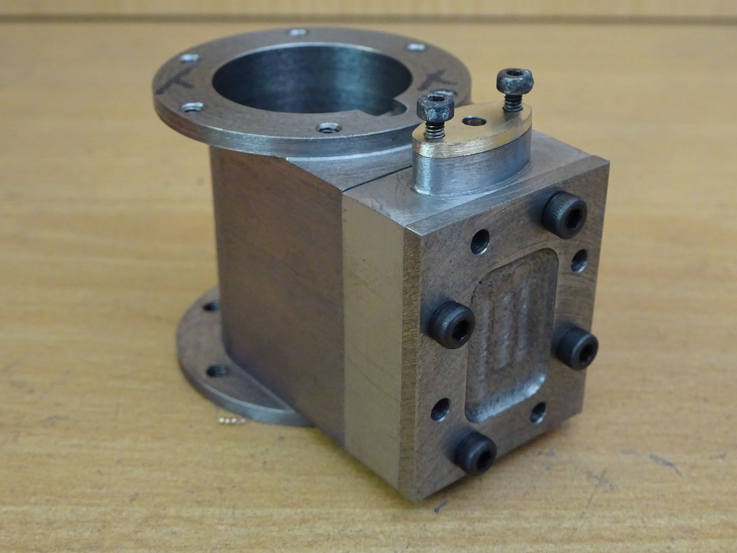
Generating an elliptical outline or hole in a plate is trivial using CNC Like the cutout in the centre of this spacer, just for the hell of it:
Andrew |
| pgk pgk | 15/07/2018 21:38:06 |
| 2661 forum posts 294 photos | If I recall one can draw an ellipse by simply using two pins spaced apart, a loop of string around them to guide a pencil and adjust either the length of string for a rounder ellipse or widen the pin spacing for a longer ellipse. That suggests one could create a holder on the mill table using two spaced bearings under a top with a circular cut-out that's guided around manually. (Watch your fingers and take light cuts) I haven't drawn that out to check but the principle of rotating around two centres should work?
pgk |
| Michael Gilligan | 15/07/2018 22:06:02 |
23121 forum posts 1360 photos | Posted by pgk pgk on 15/07/2018 21:38:06:
If I recall one can draw an ellipse by simply using two pins spaced apart, a loop of string around them to guide a pencil and adjust either the length of string for a rounder ellipse or widen the pin spacing for a longer ellipse. That suggests one could create a holder on the mill table using two spaced bearings under a top with a circular cut-out that's guided around manually. (Watch your fingers and take light cuts) I haven't drawn that out to check but the principle of rotating around two centres should work? . I think it's fair to say that the underlying geometry of that method is the same as that of the router jig that I referenced. Wikipedia shows several interesting constructions: **LINK** https://en.wikipedia.org/wiki/Ellipse ... and I suppose the Steiner method would be the basis of John's CNC approach. MichaelG. |
| duncan webster | 15/07/2018 22:16:40 |
| 5307 forum posts 83 photos | If making a gland then the end radius and overall width are givens, and possibly do not approximate to a true ellipse. If you want a good approximation then proceed as follows draw a box with the major length of the ellipse along x axis and the minor length along the y from the end of x draw a line up at 60 degrees to the x axis o'clock) from the top of the y draw a line at 15 degrees below the x axis (just before 9 o'clock) from the intersection of these 2 lines draw a line down at 60 degrees below the x axis to intersect the y axis. where this line crosses the x axis is the centre for the end radius where it crosses the y axis is the centre for the top radius all shown on picture. |
| JasonB | 16/07/2018 07:42:11 |
25215 forum posts 3105 photos 1 articles | I have done quite a few small wooden ellipses using the same principal that Michael's link to the trend jig uses, you just need a strip of wood or even the edge of a bit of paper, just mark 1/2 of each axis and then move your rod around and mark the edge of the elipse. Since I have had CAD I tend to use that to draw a suitable ellipse and then produce a set of co-ordinates, for big things like dining tables I tend to just make a jig of 1/4 of the ellipse from say 6mm MDF then use that to mark out and finally guide a router. Similar can be done for smaller metal ones just by drawing a second ellipse outside the first that is larger by half the diameter of your cutter, again you only need to work out for 1/4 of the shape and simply adjust the +/-valve . Plunge at each co-ordinate and the finish with a file. Depending on spacing and dia of cutter you can leave yourself more or less filing as you prefer.
|
| Neil Wyatt | 16/07/2018 10:50:25 |
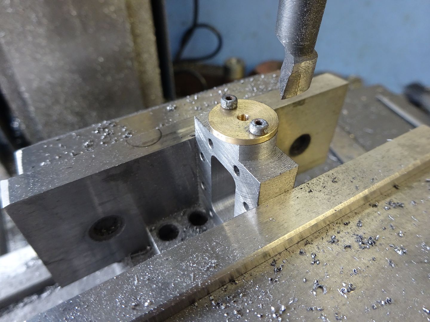
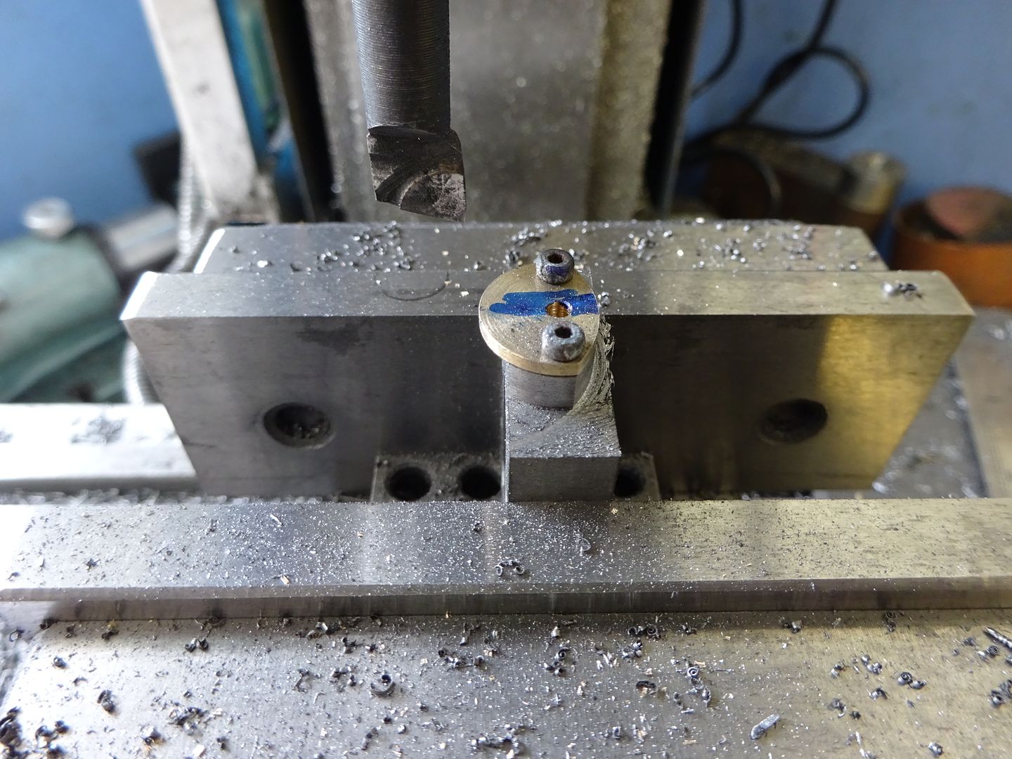
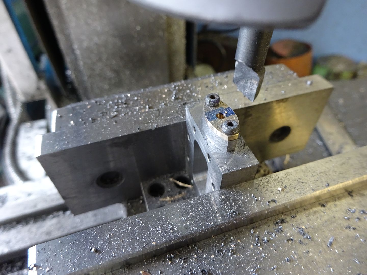
 19226 forum posts 749 photos 86 articles | Ken, The jig was just a random lump of brass of the right diameter. As jason says it was a gland, so the shape is cosmetic. It was set up by eye, all that matters is the two screw holes are the right distance apart and on the same radius. The ends were finished by filing.
|
| Ian P | 16/07/2018 11:04:42 |
 2747 forum posts 123 photos | Posted by Neil Wyatt on 16/07/2018 10:50:25:
Ken, The jig was just a random lump of brass of the right diameter. As jason says it was a gland, so the shape is cosmetic. It was set up by eye, all that matters is the two screw holes are the right distance apart and on the same radius. The ends were finished by filing.
None of the posts in this topic seem to be related to 'Ken' so I am wondering if somehow my PC does not see all the post. Neil's reply does refer to an ellipse so what am I missing? Ian P
|
| Martin Connelly | 16/07/2018 11:49:59 |
 2549 forum posts 235 photos | Turning an ellipse without a copy lathe and a suitable shape to copy may be very hard. Can we have more details of what you want to do such as material, sizes, available equipment. Milling an ellipse is easy with CNC and possible with manual bed movements and a suitable spreadsheet printout. With a CNC lathe with a servo spindle with full spindle position feedback it should be possible but without a servo spindle or spindle position feedback it could be impossible. Martin C |
| Keith Rowe | 16/07/2018 12:12:28 |
| 20 forum posts 2 photos | Thank you all for your replies I am overwhelmed by the support. I think I need to be clearer about myself and what I am trying to do. I am a 70 year old with a big problem with maths I have no background in engineering, I have a Clark 300 mini lathe and a Sieg SX2 PLUS mill, the very little knowledge I have comes from YouTube and especially this magazine, I have made several small projects from the magazine so to all those contributors thank you and please keep them coming. I am trying to make a gland for a couple of steam engines I purchased off a well known auction site, the gland would be 22mm x 11mm approx in brass because I have some brass bar of different diameter, (I think I should be using gunmettle maybe someone could advise and why, I would like to know if I am going wrong ) when I saw the photo in the mag I thought this I could do but now I am not so confident but I won't give up. UPDATE Just received an update from neil about the jig in the photo and I will give it a try confidence restored.Guidance on brass and gunmettle would be very welcome. Many Thanks to all, my knowledge is now improved. Keith. |
| Trevor Drabble | 16/07/2018 12:26:02 |
 339 forum posts 7 photos | The turning of an ellipse is a regular feature of ornamental turning , and is usually done using a Holtzapffel Ellipse chuck or similar . Search the above terms to yield a wealth of information . |
| Martin Connelly | 16/07/2018 12:37:46 |
2549 forum posts 235 photos | Keith, one way to do this would be for someone who has an understanding of the maths involved in plotting an ellipse creating a set of coordinates for you to use with you manual mill. You would use these coordinates to move a cutter around your blank to give about the correct shape for you to file smooth and to size. For instance with a 6mm cutter and the machine set to x=0 y=0 at the centre of the gland the coordinates would start off like this and would leave about 0.5mm to file away all round. It is tedious if there are a lot of points and rougher if there are less points, just a matter of picking a happy balance. These coordinates are for 1° increments so would require 360 for the complete outline. Alternate values would take 180 moves but have a slightly rougher surface etc. These are mm values but could easily be changed to inch units. A DRO would help keep track of movement. If you want either the spreadsheet that produced these numbers or a text file with the numbers on then PM me. Martin C X value Y value 0 -14.5 0.31 -14.49 0.63 -14.46 0.94 -14.42 |
| pgk pgk | 16/07/2018 13:04:02 |
| 2661 forum posts 294 photos | Keith,
There's often a simple non-math way of getting there. The first fancy shaped item I wanted to turn was simply sketched onto graph paper (free download from the web that I printed out) and then I counted the squares for my co-ordinates and depths and filed/sanded the rough outline to finish. Similarly one could just trace around an object onto square paper and, as the illustrious Jason shows, just plunge cut your way around it.
pgk |
| Ian S C | 16/07/2018 13:19:19 |
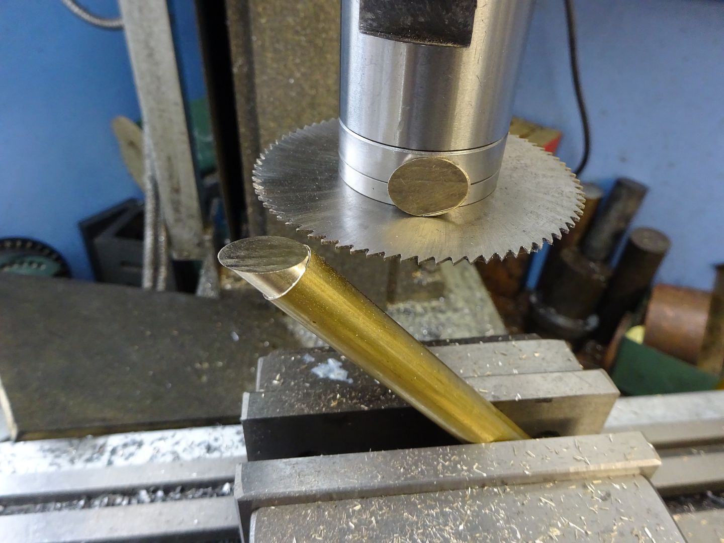
 7468 forum posts 230 photos | I wanted an oval piece of brass for the butterfly valve of a Stuart Turner S9 steam engine I was rebuilding, I turned a bit of brass rod to the minimum width, then cut it across at 20*, then moved along and another cut to make a 1 mm thick butterfly valve plate, it worked, so it must be right. Ian S C |
| JasonB | 16/07/2018 13:35:28 |
25215 forum posts 3105 photos 1 articles | Keith, if you can give the the hole size and spacing I'll sketch it out for you so you know the dia of the jig and how far out from the middle the holes need to be.
Brass will be fine as it is just going to be in contact with air or steam not the hot water which can attack brass. |

.jpg")

Please login to post a reply.
Magazine Locator
Want the latest issue of Model Engineer or Model Engineers' Workshop? Use our magazine locator links to find your nearest stockist!
Sign up to our Newsletter
Sign up to our newsletter and get a free digital issue.
You can unsubscribe at anytime. View our privacy policy at www.mortons.co.uk/privacy
Latest Forum Posts
- *Oct 2023: FORUM MIGRATION TIMELINE*
05/10/2023 07:57:11 - Making ER11 collet chuck
05/10/2023 07:56:24 - What did you do today? 2023
05/10/2023 07:25:01 - Orrery
05/10/2023 06:00:41 - Wera hand-tools
05/10/2023 05:47:07 - New member
05/10/2023 04:40:11 - Problems with external pot on at1 vfd
05/10/2023 00:06:32 - Drain plug
04/10/2023 23:36:17 - digi phase converter for 10 machines.....
04/10/2023 23:13:48 - Winter Storage Of Locomotives
04/10/2023 21:02:11 - More Latest Posts...
- View All Topics
Support Our Partners


Shopping Partners
Subscription Offer

Latest "For Sale" Ads
- Reeves** - Rebuilt Royal Scot by Martin Evans
by John Broughton
£300.00 - BRITANNIA 5" GAUGE James Perrier
by Jon Seabright 1
£2,500.00 - Drill Grinder - for restoration
by Nigel Graham 2
£0.00 - WARCO WM18 MILLING MACHINE
by Alex Chudley
£1,200.00 - MYFORD SUPER 7 LATHE
by Alex Chudley
£2,000.00 - More "For Sale" Ads...
Latest "Wanted" Ads
- D1-3 backplate
by Michael Horley
Price Not Specified - fixed steady for a Colchester bantam mark1 800
by George Jervis
Price Not Specified - lbsc pansy
by JACK SIDEBOTHAM
Price Not Specified - Pratt Burnerd multifit chuck key.
by Tim Riome
Price Not Specified - BANDSAW BLADE WELDER
by HUGH
Price Not Specified - More "Wanted" Ads...
Get In Touch!
Do you want to contact the Model Engineer and Model Engineers' Workshop team?
You can contact us by phone, mail or email about the magazines including becoming a contributor, submitting reader's letters or making queries about articles. You can also get in touch about this website, advertising or other general issues.
Click THIS LINK for full contact details.
For subscription issues please see THIS LINK.
Digital Back Issues


Donate

 Register
 Log-in
Model Engineer Magazine
- Percival Marshall
- M.E. History
- LittleLEC
- M.E. Clock

ME Workshop
- An Adcock
- & Shipley
- Horizontal
- Mill

Subscribe Now
- Great savings
- Delivered to your door

Pre-order your copy!
- Delivered to your doorstep!
- Free UK delivery!
All Forum Topics > Beginners questions > How to machine an ellipse