Forum sponsored by:

Myford ML7 spindle internal taper/counterbore?
| Hopper | 14/02/2017 12:56:18 |
 7881 forum posts 397 photos | Just looking over the world's most abused lathe that I recently picked up at a garage sale, an ML7, and noticed that the 2MT internal taper in the headstock spindle does not start at the very front of the spindle. It is counterbored parallel for almost an inch and then the 2MT taper starts. Seems a bit odd as any centre used in the headstock spindle is then sticking out almost an inch from the taper before it even starts to poke out to where it can be used. Not a great set up, one would think, with all that extra overhang. Question is: Is this the standard Myford set-up with the first inch or so of the bore parallel? Or has the abusive previous owner poked a boring bar down the spindle at some stage of its unfortunate career? Edited By Hopper on 14/02/2017 12:56:43 |
| roy entwistle | 14/02/2017 13:18:21 |
| 1716 forum posts | The taper should start at the end of the bore, nothing parallel Roy |
| not done it yet | 14/02/2017 15:20:42 |
| 7517 forum posts 20 photos | Ha ha, maybe the abusive previous owner needed to mount something longer than the bed?
This thread should be in the 'tool abuse' thread! Edited By not done it yet on 14/02/2017 15:24:59 |
| Brian Oldford | 14/02/2017 16:10:41 |
 686 forum posts 18 photos | New spindle or the bay I'd hazard.
|
| John Stevenson | 14/02/2017 16:15:54 |
 5068 forum posts 3 photos | No it's not. Out on site at moment so post later but now you have the chance to drag the design kicking and screaming into the 19th century |
| not done it yet | 14/02/2017 17:49:55 |
| 7517 forum posts 20 photos | into the 19th century Is the design that old! Would that be early or late 19th century, John? Err, 1810 or 1890 ... ish?
|
| Nick_G | 14/02/2017 17:56:46 |
 1808 forum posts 744 photos | Posted by not done it yet on 14/02/2017 17:49:55:
into the 19th century Is the design that old! Would that be early or late 19th century, John? Err, 1810 or 1890 ... ish?
. I think John was being nothing more than flippant and tongue in cheek.
Nick |
| daveb | 14/02/2017 18:57:47 |
| 631 forum posts 14 photos | Might be an ex school lathe, the little boys could work wonders with a boring tool. It's not too bad though, they usually bored the spindle nose away so the chuck fell off. |
| John Stevenson | 14/02/2017 22:24:13 |
5068 forum posts 3 photos | Could be long - go get a coffee or a drink of tea and anyone of a mild disposition or who has Myford grey in their veins might do better to log off..
First off and this is just my take on it the only reason for the MT2 in the spindle nose is to run work between centres but the smart set can still do this by leaving the 3 jaw chuck on, placing a bar in the chuck and turn a centre on it and provided that you don't remove said bar then it will run perfectly true and you can use one of the jaws to drive the carrier. Nothing new, people have been doing this for years.
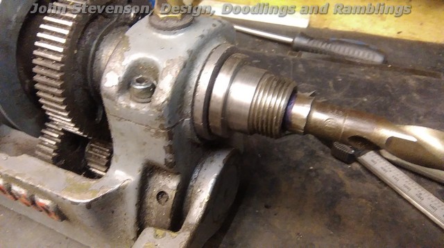
So this is a spare head stock off a ML7 with a MT 2 drill fitted to give an idea of where and how it goes..
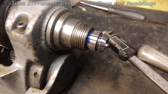
Now this is an ER20 collet offered up to a reasonable decent spindle.
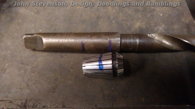
And the two compared.
As you can see the thick end of the ER20 is bigger than the MT2 but the small end is smaller than that part of a MT2.
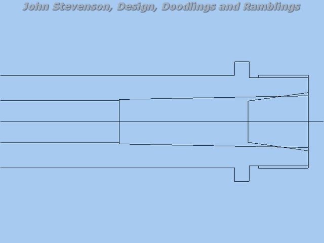
However all is not lost. Seeing as out intrepid hero, Hooper has got a stuffed up spindle to start with he's nothing to loose. So for your perusal here is a CAD [ clown assisted drawing ] of the spindle with bits superimposed.
Going from left to right in the centre we start off with a nominal 9/16" clearance hole as fitted as standard, this then develops into the MT2 and super imposed on this is the ER20 collet, all drawn to scale.
The ER 20 at the fat end is believe it or not 20mm diameter, so if the spindle was bored to say 22mm diameter for a depth of 1" and a slug of steel pressed and loctited in, then bored in situ at 8 degrees half included angle to accept an ER20 collet, all that is left is to make a new collet nut but with a 1 1/8" x 12 Whit form thread.
Job done and you now have a useful size collet system that can hold any size from 0.5mm up to 13mm. |
| Nick Hulme | 14/02/2017 23:56:58 |
| 750 forum posts 37 photos | John, That's far too logical and will never catch on I haven't stripped and had The Clown draw my ER40 roller bearing S7 head so I can't yet provide details for and suggest that as an alternative :D Edited By Nick Hulme on 14/02/2017 23:57:26 |
| Hopper | 15/02/2017 00:08:48 |
7881 forum posts 397 photos | Now, that's a darn good idea. Thank you Mr Stevenson. Instead a piece of abuse it may turn out to be an improvement after all, with a little judicious fettling! I like the idea of the ER20 collets a lot -- they are cheap as chips to buy online, even the good ones. And as you say, who ever uses the MT2? In the Mighty Drummond, I always do as you describe and use a soft centre held in the three jaw and have a couple of drive dogs made up that fit very nicely around the jaws without slapping about. I found that trying to use the "correct" live centre and catchplate leaves too much of the job over the gap in the bed and so the carriage is too far away from it for practical use. I was planning on using the MT2, though, for seating a homemade testbar to check headstock alignment when I scrape the headstock bearings in but there are other ways to skin that cat -- turned bar in three jaw etc -- so that's not a huge problem. And there is probably enough MT2 left in the spindle to get a seating good enough for initial alignment check anyways. And I remember distinctly thinking when I pulled the spindle out of the all pulleys and gears mounted on it that finally, finally I had found a piece on this lathe that does not have hammer or chisel marks on it, or other signs of abuse. So I can honestly say now that every single part of this machine bears some sign of abuse! There are even chisel marks on the pulleys.n The electricians have a lot to answer for. I'll measure up the counterbore in the spindle and see how it sits for adding collets. |
| Hopper | 16/02/2017 06:29:43 |
7881 forum posts 397 photos | Interesting. After I removed the honking great burr from the mouth of the counterbore, it measured up at exactly .750" diameter by .760 deep and appears to have been bored and either honed or emery papered to a nice finish. So pretty easy to sleeve and bore to fit ER collets as suggested. Incidentally the burr on the end was a mystery -- until I noticed the circular grooved gouged out of the end of the spindle. It looked kind of familiar. Just like the gouges in the face plate. Put them together and sho' nuff, whoever grooved up the face plate managed to get one groove spot on the end of the spindle nose. Must have been a dead blunt tool from the burr it threw up. I just can't for the life of me imagine what they were doing that caused those grooves. It obviously was not a one-time whoopsie but more of a SOP over a long period. The counterbore is clearly visible in the lower pic, as is the groove in the spindle nose.
Edited By Hopper on 16/02/2017 06:35:09 Edited By Hopper on 16/02/2017 06:44:24 Edited By Hopper on 16/02/2017 06:46:37 |
| Hopper | 16/02/2017 06:42:55 |
7881 forum posts 397 photos | Posted by daveb on 14/02/2017 18:57:47:
Might be an ex school lathe, the little boys could work wonders with a boring tool. It's not too bad though, they usually bored the spindle nose away so the chuck fell off. No this one has professional-strength abuse all over it. The spindle bore is almost nothing by comparison to the hammer marks on the bed, ten thou slack in the headstock bearings, carriage so worn it has given itself a "wide guide" conversion by wearing down the narrow guide so far the rear surface has been rubbing on the rear shear. It was used in an electric motor reconditioning workshop. If you have ever seen how electricians use hand tools (multigrips and screwdriver to do everything) you may have some idea what this poor lathe went through. A few more details of its sad life are here **LINK** |
| Mark Rand | 16/02/2017 23:33:54 |
| 1505 forum posts 56 photos | I guess this counts as an 'ex-college machine, with little use' |
| John Stevenson | 17/02/2017 00:43:48 |
5068 forum posts 3 photos | Hopper, Sorry I spelt your name wrong in my post. If you are doing the ER 20 conversion you will have to bore out to 20mm plus to get the collet in.
[Edit] No forget that it won't matter, too late at night here and any size will do it's just that there will be a transition line somewhere along the ER taper which won't matter anyway.
The ML7 spindle is quite a simple piece of turning in a non exotic steel, I believe they used EN8 left soft on the white metal version and onece you are at this stage it would not be a lot more work to make a new spindle, with a flange. D1-3 would be well overkill for a 3 1/2" lathe but a straight stepped flange similar to the Chinese C3, C4, C6 series lathes with a simple shoulder, no taper, would be very easy to replicate.
It would give you safe reversing, a source of cheap back plates and chucks.
Fitting is also very easy. Stolen from the Mini late site of a review on the Sieg SC8 lathe.
The rotating plate has three keyhole-shaped holes that rotate through about a 15-degree arc. After the nuts on the studs pass through the large end of the keyhole, the plate is rotated to bring the small end of the keyhole into place. Then the nuts are tightened down on the plate to lock the chuck securely in place. One advantage of this system is that you don't need to hold the heavy chuck in place with one hand while using the other hand to attempt to get the nuts in place in the limited space behind the spindle. Another advantage is that the nuts stay with the chuck, so are much less likely to get lost or to drop into the gap between the ways as you're trying to install them. A third advantage is that installing and removing the chuck is quicker.
I have this system on my TOS with A1-4 chucks fitted, it's quick as the nuts always stay on the studs and it's impossible for them to vibrate loose as sometimes the D series camlock can under interupted cuts. |
| Hopper | 17/02/2017 02:08:33 |
7881 forum posts 397 photos | Certainly food for thought there JS. At this stage, shed time being very limited, the goal is to get to "Stage One" and get it cleaned up, inspected, painted and back together in a basic useable manner so I can see if I like using it as much as or more than the Mighty Drummond and make a decision on whether I keep it or not. Then if I decide to keep it I will make such mods as make it more useable. I like the idea of the flanged spindle and standard chucks, although the two chucks with it, original Burnerds, seem to be in good nick, especially the four jaw. The poor old faceplate seems to have been the preferred victim. Would the flange on those spindles just be pressed and loctited into position then machined true, or are they welded? (I'm sure the esteemed gentlemen in the Orient don't waste material machining them from the solid out of 100mm bar etc. |
| Hopper | 17/02/2017 02:12:23 |
7881 forum posts 397 photos | Posted by Mark Rand on 16/02/2017 23:33:54:
I guess this counts as an 'ex-college machine, with little use' Yes, the "College of Hard Knocks". |
| John Stevenson | 17/02/2017 02:27:23 |
5068 forum posts 3 photos | They start off as a forging, easy way to save money and material. |
| Hopper | 17/02/2017 04:40:48 |
7881 forum posts 397 photos | Posted by John Stevenson on 17/02/2017 02:27:23:
They start off as a forging, easy way to save money and material. Might be a bit beyond my workshop capabilities. Only forging I've done was my mother's signature on sick notes to school. But I suppose welded, stress relieved and machined would do the job. |
| Ian S C | 17/02/2017 10:10:19 |
 7468 forum posts 230 photos | Hopper, I wonder if they used the face plate for cutting some form of gasket, or thin washer without using an expendable backing, that would give you the grooves. Ian S C |


Please login to post a reply.
Magazine Locator
Want the latest issue of Model Engineer or Model Engineers' Workshop? Use our magazine locator links to find your nearest stockist!
Sign up to our Newsletter
Sign up to our newsletter and get a free digital issue.
You can unsubscribe at anytime. View our privacy policy at www.mortons.co.uk/privacy
Latest Forum Posts
- *Oct 2023: FORUM MIGRATION TIMELINE*
05/10/2023 07:57:11 - Making ER11 collet chuck
05/10/2023 07:56:24 - What did you do today? 2023
05/10/2023 07:25:01 - Orrery
05/10/2023 06:00:41 - Wera hand-tools
05/10/2023 05:47:07 - New member
05/10/2023 04:40:11 - Problems with external pot on at1 vfd
05/10/2023 00:06:32 - Drain plug
04/10/2023 23:36:17 - digi phase converter for 10 machines.....
04/10/2023 23:13:48 - Winter Storage Of Locomotives
04/10/2023 21:02:11 - More Latest Posts...
- View All Topics
Support Our Partners


Shopping Partners
Subscription Offer

Latest "For Sale" Ads
- Reeves** - Rebuilt Royal Scot by Martin Evans
by John Broughton
£300.00 - BRITANNIA 5" GAUGE James Perrier
by Jon Seabright 1
£2,500.00 - Drill Grinder - for restoration
by Nigel Graham 2
£0.00 - WARCO WM18 MILLING MACHINE
by Alex Chudley
£1,200.00 - MYFORD SUPER 7 LATHE
by Alex Chudley
£2,000.00 - More "For Sale" Ads...
Latest "Wanted" Ads
- D1-3 backplate
by Michael Horley
Price Not Specified - fixed steady for a Colchester bantam mark1 800
by George Jervis
Price Not Specified - lbsc pansy
by JACK SIDEBOTHAM
Price Not Specified - Pratt Burnerd multifit chuck key.
by Tim Riome
Price Not Specified - BANDSAW BLADE WELDER
by HUGH
Price Not Specified - More "Wanted" Ads...
Get In Touch!
Do you want to contact the Model Engineer and Model Engineers' Workshop team?
You can contact us by phone, mail or email about the magazines including becoming a contributor, submitting reader's letters or making queries about articles. You can also get in touch about this website, advertising or other general issues.
Click THIS LINK for full contact details.
For subscription issues please see THIS LINK.
Digital Back Issues


Donate

 Register
 Log-in
Model Engineer Magazine
- Percival Marshall
- M.E. History
- LittleLEC
- M.E. Clock

ME Workshop
- An Adcock
- & Shipley
- Horizontal
- Mill

Subscribe Now
- Great savings
- Delivered to your door

Pre-order your copy!
- Delivered to your doorstep!
- Free UK delivery!
All Forum Topics > Manual machine tools > Myford ML7 spindle internal taper/counterbore?