Forum sponsored by:

piston rings vs. silicone o-ring
| John gallo | 26/01/2016 13:02:58 |
| 26 forum posts | I am new to this forum and look forward to a great experience. As a novice modeler I took on the project of machining a Stuart beam engine. Everything is going pretty well and I am at the point of turning the piston. The plans call for a silicone o-ring but there is the option of using two metal piston rings instead. Is there any advantage to using the rings over the silicone o-ring? I have the two metal rings, but they don't come with any information on piston groove size or position on the piston. The piston is one inch in diameter by one half inch thick. I contacted the company but they had no information on groove clearances. If any one has had any experience with some thing like this I would appreciate any help I could get as I am leaning towards the metal rings over the o-ring. Thanks in advance, John. |
| JasonB | 26/01/2016 17:36:07 |
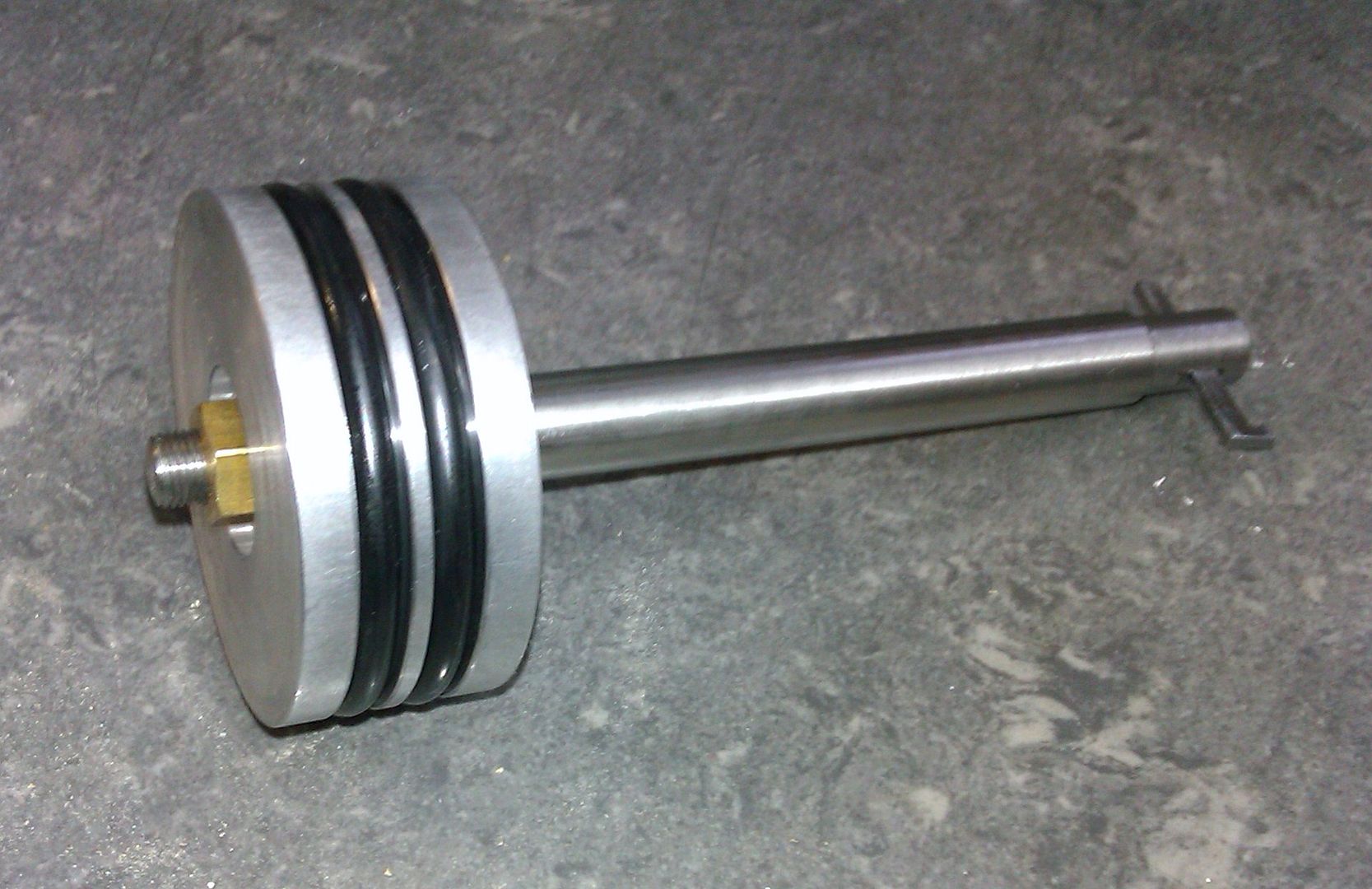
 25215 forum posts 3105 photos 1 articles | Assuming you have 1/16" wide rings I would cut two grooves with 1/16" of material left between the two grooves. They should be cut just wide enough for the ring to fit into without sticking so something like 0.064" which would leave you with just short of 3/32" each end if set out centrally on teh piston. Depth of the groove should be about 0.005" more than the thickness of the ring. Although this pic shows O rings I would place the iron ones in similar way.
Edited By JasonB on 26/01/2016 17:39:18 |
| John gallo | 01/02/2016 22:29:37 |
| 26 forum posts | Thanks for the advice, however I made a mistake in the original post. The piston is one quarter inch thick not one half. It calls for two 1/16" rings in the catalogue, but I don't see how to place them. It seems like there isn't enough room on the piston. If I space them evenly there will be just shy of 3/64" in the middle and on the ends. Does this sound like enough? I wish Stuart would have offered some help, but they say they have no dimensions for this detail. |
| John gallo | 01/02/2016 22:59:30 |
| 26 forum posts | Just another thought. Is it possible the two rings should go together next to each other in a 1/8" groove in the center of the piston? |
| Jens Eirik Skogstad | 02/02/2016 06:14:16 |
 400 forum posts 22 photos | Posted by John gallo on 01/02/2016 22:59:30:
Just another thought. Is it possible the two rings should go together next to each other in a 1/8" groove in the center of the piston? No, it must be 2 groove in piston with 1/16" wide groove. Be carefull when you are turning the groove: Use sharp tool and fine feed speed turned by hand to make smooth surface in piston ring groove to preventing leakage between piston ring and groove. Not sloppy fit and no sticking piston ring in groove. The piston ring in cylinder: Be sure the gap is not too big. 0.008" -0.01" ring gap is prefered in the steam engine. |
| Ian S C | 02/02/2016 09:07:45 |
 7468 forum posts 230 photos | When I rebuilt a Stuart Turner S9 I found that the piston had one .250 wide groove, no rings, the book says 2 rings, so I made and fitted 2 rings .125" wide. Ian S C |
| John gallo | 02/02/2016 09:40:57 |
| 26 forum posts | Ian, do you feel that 2 metal rings in one groove is superior to one silicone o-ring? |
| Tim Stevens | 03/02/2016 15:40:19 |
 1779 forum posts 1 photos | A split metal piston ring works because pressure gets behind it and pushes it outwards against the bore, and downwards against the top of the land below it. It is therefor important that the bore, and the flat faces of the grooves, are properly flat, as well as both faces of the ring. In an IC engine the ring needs only the bottom groove face to be really flat, of course. O rings can work in the same way, but I suspect that they do not have the self lube properties of a cast iron ring, and might suffer from stiction (ie jerkiness) at low rotational speeds. The proper name for these split metal compression rings is 'Ramsbottom's Metallic Packing'. They were invented (about 1870) by the same railway engineer that thought of the water trough for filling the tender at speed. I wonder why I have not seen one of those in use on a garden railway? Cheers, Tim |
| Brian John | 25/03/2016 06:34:35 |
| 1487 forum posts 582 photos | What about Teflon piston rings ... how do they compare ? When I built the 3BIM and 7BIM steam engines from PM Research they were supplied with Teflon piston rings which have worked very well. Does anybody make Teflon piston rings for model engineers ...say, 10mm, 12mm or 15mm ? |
| John Fielding | 25/03/2016 07:20:03 |
| 235 forum posts 15 photos | The use of O rings in square cut grooves as used for cast iron rings is a poor solution. O rings are meant to fit into semicircular grooves so they can roll as the piston slides in the cylinder. A square groove means the ring bunches up against a flat surface and it doesn't roll but gets squeezed out into closer contact with the bore and high wear rates occur. If there are ports in the liner then it gets the bacon slicer treatment as it gets shaved on every stroke! I have used PTFE square rings, Vesconite rings, bronze rings, dural rings, mild steel and cast iron rings with varying degrees of success. If I had the choice then it would be either bronze or mild steel in a cast iron sleeve liner. For a gunmetal or bronze liner then CI or mild steel is the best, but my 3 1/2" Netta has dural rings and they work fine. Even the D-slide valves are dural and they show almost zero wear if the lubrication is up to scratch. In a mechanical engineering textbook I read that for steam engines operating at low pressure - ie below 250psi - then pistons with NO rings have very little leakage compared to ones with rings. In fact no grooves and a plain piston works perfectly well as long as the piston fit is correct. Many model aero engines of the compression ignition types never had rings fitted and the combustion pressure in that sort of engine is ten times or more of a steam engine. Piston compressors in fridges similarly have no rings on the pistons. In my experiments I found that a groove in the piston without a ring works only slightly less well than a piston with a ring, it is a labyrinth seal, same as a piston with a ring. The major difference is in the friction, the piston with a ring has considerably more friction and friction in small engines robs power. In steam engines the condensate which forms in the bore is an adequate piston to liner lubricant and seal when cast iron is used. Look at the piston in a Crosby Indicator to see how well it seals, it has a single groove with no ring and it seals perfectly! The condensate fills up the groove and acts like a flexible ring. The friction is virtually zero! |
| Brian John | 25/03/2016 07:46:07 |
| 1487 forum posts 582 photos | So for a gunmetal piston (10mm to 15mm) in a brass cylinder on a small steam engine, you recommend that no piston rings be used ? Edited By Brian John on 25/03/2016 07:46:27 |
| John Fielding | 25/03/2016 08:58:38 |
| 235 forum posts 15 photos | Hi Brian, I wouldn't have thought one necessary for something that small. Look at the Mamod steam engines which use a similar size bore, no rings ever used. They used brass for the piston and liner and apart from the occasional drop of oil when starting would run for years on and off with very little wear. Brass on brass is not a good combination but the choice was driven by cost. The piston and bore were over time burnished to a high polish and the friction was close to zero. As I mentioned earlier, friction in small engines is a major problem. If fitting a ring increases the load significantly then the poor thing is gutless. If you put a tiny groove, say 1.5mm wide and about 0.5mm deep it will form a labyrinth seal which will be a bit better, it will tend to hold a little oil and condensate etc, but you would be hard pressed to measure the difference. The little loss of piston surface area means the friction reduces a tad but it is so small it is insignificant. In model IC engines of the compression ignition and glow plug variety very few used rings and the piston speeds of those engines were very high compared to a steam engine. As long as the bore and piston are finished to a good polish then the friction will be low and running improves the surface finish even more. Cast iron when well polished with running has a glass hard surface, but it also has millions of tiny inclusions which hold graphite and the odd bit of oil or condensate, meaning the friction is very low. Bronze and gunmetal don't have this benefit and any loss of lubricant can make them seize suddenly when the oil film is lost. The real reason why piston rings are fitted to motor car engines using a cast iron liner or block is because of the piston material. Before WW1 when WO Bentley experimented with light alloy pistons in his aero engines all engines used either cast iron or steel pistons. Now steel and cast iron have very similar rates of expansion. If the piston and liner are cast iron then the expansion is exactly the same and the clearance between the two is virtually constant. Steel is very close to cast iron, steel is simply iron with a lot less carbon, so you would expect them to be similar. But aluminium alloy pistons expand at almost the twice the rate as cast iron. So when the engine is cold it rattles around in the bore, but when up to working temperature it closes up the clearance. This looseness causes a knocking noise when cold called "Piston Slap" as the piston is slapping on the bore as it goes up and down when cold. If they overheat then they go tight and they can seize. To allow the alloy piston to change in diameter but still maintain a good gas seal you need another mechanism, ie piston rings made of cast iron. Very few engines used piston rings until about the 1860s, before that they simply relied on a good fit. Early Newcomen engines used a grooved piston with "junk rope" seals soaked in water on the wooden piston. But in those days they couldn't machine cylinders, they were used as cast.
|
| KWIL | 25/03/2016 10:58:08 |
| 3681 forum posts 70 photos | John F, O rings "roll" in their grooves when sliding in a cylinder? Evidence and justification? |
| duncan webster | 25/03/2016 12:00:30 |
| 5307 forum posts 83 photos | I've looked at lots of hydraulic cylinders with O ring seals and never yet seen one with a semi circular groove. All have been just rectangular. For a comprehensive guide see **LINK** There is lots of successful experience using silicone O rings in steam engines with bronze cylinders, not too sure about cast iron, someone out there will know Edited By duncan webster on 25/03/2016 12:02:11 |
| Neil Wyatt | 25/03/2016 15:25:00 |
 19226 forum posts 749 photos 86 articles | I've had a single silicone o-ring in the piston of my Stuart 10V (3/4" diameter, square groove) since about 1999/2000. These days I only run it about once a year, sometime son air, occasionally on steam. Still running well on the original ring. I imagine the beam engine will be exp[ected to perform similarly relaxed duties. Tubal Cain did a lot of calcs for rings in steam engines and without exception he found that all the examples he looked at had far too high pressure (and therefore friction and wear) and were better suited to IC engines than steam, engine that need very little pinch force. Many other people have suggested that a single or pair of grooves are as effective as a ring in small engines, the reduced friction more than compensating for any blow by. > Early Newcomen engines used a grooved piston with "junk rope" seals soaked in water on the wooden piston. But in those days they couldn't machine cylinders, they were used as cast Boulton and Watt couldn't get their engines to work successfully until John Wilkinson to make their cylinders with his cannon boring machine. |
| Lambton | 25/03/2016 16:53:56 |
 694 forum posts 2 photos | The late Arnold Throp of Dore Engineering and author of "Vertical Milling in the Workshop" published some articles on the application of O rings in model engineering in ME September and October 1964. These articles were collected together in a booklet and sold by Dore Engineering for 3 shillings (15p) I still have my copy. |
| Peter Krogh | 25/03/2016 17:23:46 |
 228 forum posts 20 photos | O-rings rolling in semi-circular grooves??? Fantastically outlandish!! Such a statement makes the rest of your 'information' highly suspicious. Decades of seal gland experience and such a thing was never seen in practice or the professional literature. Goes against everything to do with O-rings!! Pete
|
| Steve Withnell | 25/03/2016 17:49:06 |
 858 forum posts 215 photos | The Stuart Victoria piston has an 'o' ring in a square groove. This piston design is common to the Beam, Coombes and all the other engines which use the 1 inch diameter cylinder. Steve |
| John Fielding | 26/03/2016 09:28:45 |
| 235 forum posts 15 photos | For all the doubters of the O-ring rolling in the groove, perhaps the following from Parker Seals technical documents will clarify the situation. In a reciprocating seal, there is relative reciprocating motion (along the shaft axis) between the inner and outer elements. This motion tends to slide or roll the O-ring, or sealing surface at the O-ring, back and forth with the reciprocal motion. Examples of a reciprocating seal would be a piston in a cylinder, a plunger entering a chamber, and a hydraulic actuator with the piston rod anchored. Figure 1-9 illustrates a typical reciprocating seal. Further more they give not only performance data but also recommended groove shapes and necessary radius for a typical groove for different applications. The seminal paper of the use of O-rings was by D R Pearl in 1947 presented at a conference of the American SAE. In it Pearl gave some diagrams of how O-rings behave when used as sealing rings in a reciprocating application. His diagram is shown here. Note the O-ring does not fill the groove when static or moving.
Furthermore, Parker Seals in their technical data give recommended groove shapes for reciprocating sealing rings as seen here.
You will note several important points. Firstly, the groove must NOT be square cut as per a normal piston ring. It should also have a V shape with shallow slopes and the bottom corners must be radiused as is the top transition to the piston wall. Also note the recommended back up pieces shown which makes the O-ring roll properly in semi-circular side cheeks. A square cut groove will not allow the O-ring to work as intended. Refer back to Pearl's original diagram and see how much sideways movement is needed for the O-ring to work correctly. Tight grooves result in poor sealing. So there is the evidence, if anybody knows any different then please enlighten us.
|
| Ian S C | 26/03/2016 09:33:30 |
7468 forum posts 230 photos | I seem to remember something in ME (must have been 20 yrs ago) about O rings as piston seals, the groove is rectangular, about 1.5 times the diameter of the section of the ring to allow the ring to roll. Remember that you can't compress rubber, only distort it. Originally O rings were designed for rotary, and fixed sealing, not sliding, it may have been model engineers that took them and changed the use. On another forum someone cane up with a different type of O ring, the cross section is square, but in the form of 4 lobes, so it won't roll, I'm waiting to see if he has success, he wants to use it on the piston of a hot air engine. Ian S C |


Please login to post a reply.
Magazine Locator
Want the latest issue of Model Engineer or Model Engineers' Workshop? Use our magazine locator links to find your nearest stockist!
Sign up to our Newsletter
Sign up to our newsletter and get a free digital issue.
You can unsubscribe at anytime. View our privacy policy at www.mortons.co.uk/privacy
Latest Forum Posts
- hemingway ball turner
04/07/2025 14:40:26 - *Oct 2023: FORUM MIGRATION TIMELINE*
05/10/2023 07:57:11 - Making ER11 collet chuck
05/10/2023 07:56:24 - What did you do today? 2023
05/10/2023 07:25:01 - Orrery
05/10/2023 06:00:41 - Wera hand-tools
05/10/2023 05:47:07 - New member
05/10/2023 04:40:11 - Problems with external pot on at1 vfd
05/10/2023 00:06:32 - Drain plug
04/10/2023 23:36:17 - digi phase converter for 10 machines.....
04/10/2023 23:13:48 - More Latest Posts...
- View All Topics
Support Our Partners


Shopping Partners
Subscription Offer

Latest "For Sale" Ads
- Reeves** - Rebuilt Royal Scot by Martin Evans
by John Broughton
£300.00 - BRITANNIA 5" GAUGE James Perrier
by Jon Seabright 1
£2,500.00 - Drill Grinder - for restoration
by Nigel Graham 2
£0.00 - WARCO WM18 MILLING MACHINE
by Alex Chudley
£1,200.00 - MYFORD SUPER 7 LATHE
by Alex Chudley
£2,000.00 - More "For Sale" Ads...
Latest "Wanted" Ads
- D1-3 backplate
by Michael Horley
Price Not Specified - fixed steady for a Colchester bantam mark1 800
by George Jervis
Price Not Specified - lbsc pansy
by JACK SIDEBOTHAM
Price Not Specified - Pratt Burnerd multifit chuck key.
by Tim Riome
Price Not Specified - BANDSAW BLADE WELDER
by HUGH
Price Not Specified - More "Wanted" Ads...
Get In Touch!
Do you want to contact the Model Engineer and Model Engineers' Workshop team?
You can contact us by phone, mail or email about the magazines including becoming a contributor, submitting reader's letters or making queries about articles. You can also get in touch about this website, advertising or other general issues.
Click THIS LINK for full contact details.
For subscription issues please see THIS LINK.
Digital Back Issues


Donate

 Register
 Log-in
Model Engineer Magazine
- Percival Marshall
- M.E. History
- LittleLEC
- M.E. Clock

ME Workshop
- An Adcock
- & Shipley
- Horizontal
- Mill

Subscribe Now
- Great savings
- Delivered to your door

Pre-order your copy!
- Delivered to your doorstep!
- Free UK delivery!
All Forum Topics > Beginners questions > piston rings vs. silicone o-ring