Forum sponsored by:

The Workshop Progress Thread
Report your modelling and workshop milestones in this thread.
| Neil Wyatt | 03/10/2015 22:39:47 |
 19226 forum posts 749 photos 86 articles | Right, this thread is strictly for engineering activities. Anything else will be moved to the What Did You Do Today thread. Neil |
| Simon Collier | 04/10/2015 06:46:23 |
 525 forum posts 65 photos | OK, this is definitely engineering and also, i definitely did it today. After finishing a 5" gauge Blowfly recently, I have gone back to a "on the back burner" project, a gauge 1 Eric, from Brian Wilson's book. I must say I find this very demanding and fiddly. I would rather be making 5" stuff. I am working on the cylinders, and I just machined the front covers. For me, my digital readout on the lathe is essential for this tiny stuff. I just bought a new one, for $A 550, because my old one failed. Naturally, no replacement board was available. After fuming for 2 year, I caved in. During this time the old one worked sometimes, so I only did critical work if it deigned to work that day. Finally it fully packed it in. Eric has slide valves and full Walschaearts gear, and although I have laser cut rods and links, etc., it is going to be like watchmaking trying to get it all together. The cylinders are almost done, with only the back covers to make. I should go back to the workshop now, but it is a hot day and a beer has more appeal. Beer cans are engineering! |
| JasonB | 04/10/2015 17:21:10 |
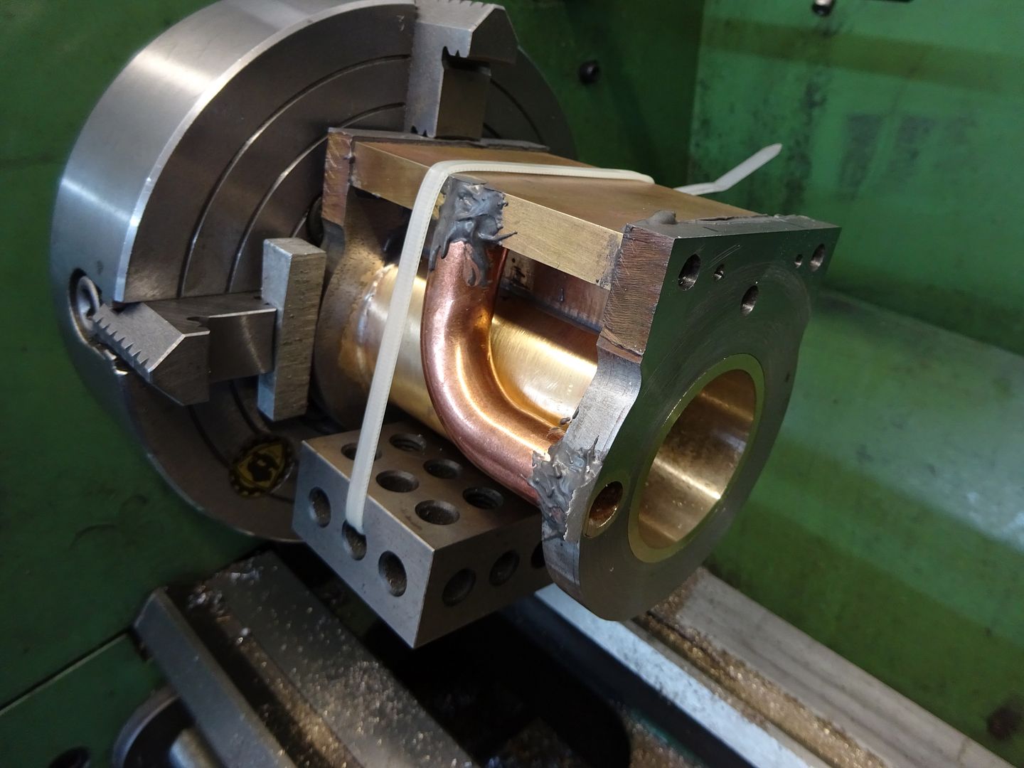
 25215 forum posts 3105 photos 1 articles | With the JBWeld set on the Tidman cylinder it could be treated like any other casting and bored & faced to size.
|
| mick70 | 04/10/2015 17:53:40 |
| 524 forum posts 38 photos | spent day making some collet blanks for my ml6, as none of ones that came with it fit stuff i will be using it for. |
| ChrisH | 04/10/2015 20:06:18 |
| 1023 forum posts 30 photos | Having made a part for a sleeve valve engine, and very pleased with completed part, was brought down to earth today with a bump by realising I had make a basic mistake in not ensuring a bearing - that fits in one end of the part - would actually fit. So today had to make a tapered mandrel to hold the part so I could machine out the end so the bearing would fit. Mandrel completed today - in between tending to coolant problems (and low oil) in my daughters car - and part fits on it beautifully, to be 'technically adjusted' tomorrow so that the bearing will be a nice push fit! Chris |
| ChrisH | 05/10/2015 19:14:46 |
| 1023 forum posts 30 photos | Following on from yesterday's post, here is the part in question mounted on the mandrel with the bearing half in being just a push fit into the part. First part complete!
Edited By ChrisH on 05/10/2015 19:27:37 |
| John Thorne | 06/10/2015 18:12:44 |
 19 forum posts 9 photos | I have made these over the last three days. 2 lubricating cocks and 2 drain cocks for full size Westinghouse air compressors as fitted to the engines on the Isle of Wight Steam Railway John |
| John Hinkley | 06/10/2015 19:30:08 |
 1545 forum posts 484 photos | I've moved here from the "What did you do today" thread. Today, I made more progress on fitting the DRO scales to my mill. This time it's the Y-axis' turn for the treatment. Now that I've two axes fitted, I feel confident that the Z-axis will be a breeze!
A bit out of focus, but it was dark when I took the photo and the flash rather made me jump! Anyhow, I think you get the gist. The cabling from the X-axis read head and the power feed motor are strapped to the mounting plate to keep them out of the way and to try to neaten that arrangement.
A view from slightly below to show the general arrangement of the brackets supporting the read head. Travel limit device has yet to be refitted as has the mill motor control box (a bit lower than originally). Maybe tomorrow. Then on to the Z-axis. I've measured the slope of the main casting and I reckon it's as near as makes no difference 3°. I've milled that angle on the end of a piece of 25mm square bar by clamping it in the mill vice with 5mm drills at 100mm between centre distance on either side of the bar. Just got to drill through for mounting bolts and find the best place to fit them. More to come . . . . . . John |
| Neil Wyatt | 06/10/2015 19:40:40 |
19226 forum posts 749 photos 86 articles | This thread isn't just for showing - people can comment too! Neil |
| Emgee | 06/10/2015 21:34:41 |
| 2610 forum posts 312 photos | Nice work John Thorne. Emgee |
| Roderick Jenkins | 08/10/2015 17:28:37 |
 2376 forum posts 800 photos | Finished my Lammas Hardness tester:
Not sure why the paintwork looks quite so awful in the photo! Cheers, Rod |
| Roger Williams 2 | 08/10/2015 17:39:37 |
| 368 forum posts 7 photos | John Thorne, lovely work there. Worth an article in MEW . |
| Neil Wyatt | 08/10/2015 17:39:58 |
19226 forum posts 749 photos 86 articles | Congratulationss to all on their handiwork, thanks for posting. Dave Lammas had some very nice ideas for tools and models. Neil |
| Michael Cox 1 | 08/10/2015 18:16:22 |
| 555 forum posts 27 photos | Rod, Where is the design for the hardness tester published. Mike |
| Roderick Jenkins | 08/10/2015 18:56:21 |
2376 forum posts 800 photos | Mike, Model Engineer 1989. Blackgates sell the castings, drawings and reprints of the articles. Cheers, Rod |
| Bob Brown 1 | 08/10/2015 18:57:50 |
 1022 forum posts 127 photos | John Thorne, Nice job, I assume you make stuff for Isle of Wight steam railway so full size and you are also like me an Islander or at least now live here. Bob |
| John Thorne | 08/10/2015 19:31:04 |
19 forum posts 9 photos | Hi Everyone Thanks for the nice coments I was very please with the way they turned out. The material used was SAE 660 and the machines used were a Myford ML7R and a mill I bought from Amadeal several years ago. Bob yes I am a Islander and volunteer at Havenstreet although the cocks were made in my own workshop at home John |
| John Stevenson | 09/10/2015 22:45:09 |
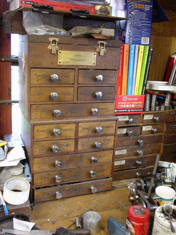
 5068 forum posts 3 photos | I have a penchant for wooden toolboxes, engineers type that is. I also have some that I have made over the years although I am not a good woodworker or really have an interest in it. More an interest in nice boxes. We had a truck garage up until 1990 when we closed the doors as lease hire was killing the game. In hindsight and for other reasons it was the best thing we could have done. We closed at end of January 1989 and spent the whole of January closing up and selling off but there wasn't a lot to sell but we still had to be there. So I took a saw bench and small router bench to work and cut then up and made some toolboxes for my next job.
The knobs were added later from the other job as these are what holds the action into a grand piano. So enough waffling about the past and fast forward to today.
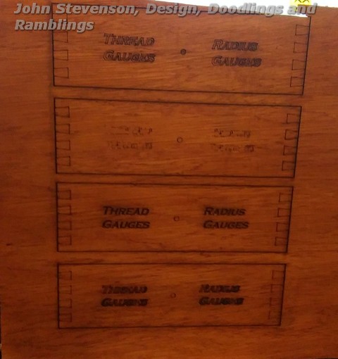
Three examples [ one didn't come out, weird font ] top and bottom are cut letters at low power, third one down is engraved or scanned. This is just a bit of crappy ply packing case sprayed afterwards with a rattle can of easing oil to get a uniform finish. Certainly looks promising and needs a bit more input. |
| Michael Gilligan | 09/10/2015 23:31:13 |
 23121 forum posts 1360 photos | Posted by John Stevenson on 09/10/2015 22:45:09:
... So what about fudging it. The laser can cut as well as engrave where wood is concerned, so what about engraving the lines of the dovetail joints whilst still using a quick half lap joint ? . It was a good story until you got to that bit, John I regret that it reminds me of self-adhesive PVC "Carbon Fibre" No thank you. MichaelG. Edited By Michael Gilligan on 09/10/2015 23:32:02 |
| John Stevenson | 09/10/2015 23:47:15 |
5068 forum posts 3 photos | Nice of you to offer to make me some proper ones then Michael. |


This thread is closed.
Magazine Locator
Want the latest issue of Model Engineer or Model Engineers' Workshop? Use our magazine locator links to find your nearest stockist!
Sign up to our Newsletter
Sign up to our newsletter and get a free digital issue.
You can unsubscribe at anytime. View our privacy policy at www.mortons.co.uk/privacy
Latest Forum Posts
- *Oct 2023: FORUM MIGRATION TIMELINE*
05/10/2023 07:57:11 - Making ER11 collet chuck
05/10/2023 07:56:24 - What did you do today? 2023
05/10/2023 07:25:01 - Orrery
05/10/2023 06:00:41 - Wera hand-tools
05/10/2023 05:47:07 - New member
05/10/2023 04:40:11 - Problems with external pot on at1 vfd
05/10/2023 00:06:32 - Drain plug
04/10/2023 23:36:17 - digi phase converter for 10 machines.....
04/10/2023 23:13:48 - Winter Storage Of Locomotives
04/10/2023 21:02:11 - More Latest Posts...
- View All Topics
Support Our Partners


Shopping Partners
Subscription Offer

Latest "For Sale" Ads
- Reeves** - Rebuilt Royal Scot by Martin Evans
by John Broughton
£300.00 - BRITANNIA 5" GAUGE James Perrier
by Jon Seabright 1
£2,500.00 - Drill Grinder - for restoration
by Nigel Graham 2
£0.00 - WARCO WM18 MILLING MACHINE
by Alex Chudley
£1,200.00 - MYFORD SUPER 7 LATHE
by Alex Chudley
£2,000.00 - More "For Sale" Ads...
Latest "Wanted" Ads
- D1-3 backplate
by Michael Horley
Price Not Specified - fixed steady for a Colchester bantam mark1 800
by George Jervis
Price Not Specified - lbsc pansy
by JACK SIDEBOTHAM
Price Not Specified - Pratt Burnerd multifit chuck key.
by Tim Riome
Price Not Specified - BANDSAW BLADE WELDER
by HUGH
Price Not Specified - More "Wanted" Ads...
Get In Touch!
Do you want to contact the Model Engineer and Model Engineers' Workshop team?
You can contact us by phone, mail or email about the magazines including becoming a contributor, submitting reader's letters or making queries about articles. You can also get in touch about this website, advertising or other general issues.
Click THIS LINK for full contact details.
For subscription issues please see THIS LINK.
Digital Back Issues


Donate

 Register
 Log-in
Model Engineer Magazine
- Percival Marshall
- M.E. History
- LittleLEC
- M.E. Clock

ME Workshop
- An Adcock
- & Shipley
- Horizontal
- Mill

Subscribe Now
- Great savings
- Delivered to your door

Pre-order your copy!
- Delivered to your doorstep!
- Free UK delivery!
All Forum Topics > Work In Progress and completed items > The Workshop Progress Thread