Forum sponsored by:

Lathe design not keeping up
| Bowber | 24/06/2015 14:01:36 |
| 169 forum posts 24 photos | Posted by Jon on 23/06/2015 12:12:30:
Good idea carries some weight. My only concern would be the belt flex/play over solid interlocking gears.
I think there will be less backlash than a full set of gears with running clearance, plus the backlash will be damped rather than able to vibrate between the 2 extreames. It's a good idea and now has me thinking of how to apply it to my Warco WM280, the compound gear set would be hard to replace with a straight belt drive from spindle to leadscrew gearbox input and keep the feeds slow enough. Steve |
| Cabinet Enforcer | 24/06/2015 16:03:44 |
| 121 forum posts 4 photos | John, for noise reduction get a tube of sikaflex or similar (used for sticking on car bodykits) and spread it evenly across the cover at maybe 1 or 2mm thick. (On the inside of the cover, obviously). If you do this to sheet steel, it turns a 'ring' into a dull thud, I suspect it will also have a marked effect on the resonant drumming from the fibreglass. |
| Phil Whitley | 24/06/2015 18:48:45 |
 1533 forum posts 147 photos | I love the spline broaching bush! Like all brilliant ideas, simple, yet elegant, the mark of true genius. (now youre going to tell me it wasnt your idea) Phil |
| John Stevenson | 24/06/2015 19:53:28 |
 5068 forum posts 3 photos | Wasn't my idea.
Been araound for years, I have seen it in old turn of the Century [ 20th century ] books. I have posted similar before when I made a new coupling for a fork truck motor and these pics were dated 2008 but it isn't new. The Victorians invented all the good stuff, only materials and electronics stopped them going further. |
| paul gough | 25/06/2015 06:24:36 |
| 10 forum posts | As far as I know the German manufacturer Wabeco uses belt drives for feed and screwcutting on their bar and prismatic bed lathes. Speed range is claimed to be 30 to 2300 RPM on the 4inch models. Would love to know peoples experience with these lathes but they appear to be non existent in the English speaking world if my post requesting comments by users is anything to go by. Paul Gough. |
| john carruthers | 25/06/2015 07:49:40 |
 617 forum posts 180 photos | Good system with little or no belt stretch, and you can specify reduced backlash pulleys. Edited By john carruthers on 25/06/2015 07:52:09 |
| John Stevenson | 26/06/2015 00:22:57 |
5068 forum posts 3 photos | Not really about keeping up with design but though I'd keep it all in this thread about the Bantam so it's searchable.
Next job is to fit a DRO. This is also applicable to a Chipmaster as they share the same saddle and it's not a good design to fit a DRO to. This is what you are faced with.
There is a groove machined into the saddle either side but it's not wide enough to take the scale. Add to this these lathes have the slot for the compound bolts in the side of the cross side so you cannot cover these up. Result is the whole lot has to stick out the back and into the air. Asked around for pictures as to people who have done this and everyone has had the same problem.
This is a typical one.
Which puts the scale right out the back, sticking up above the cross slide by 1/2" and needs a further 1" at the rear. In all fairness this is about the best you will get fitting even the slim profile glass scales. Possibly do better with a Newall system but these are not budget systems.
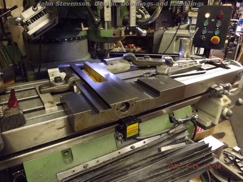
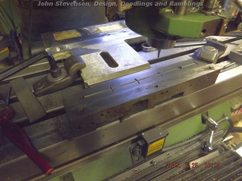
So staring at this and wondering how I can do better I decided to remove the carriage to have a better look. It was slated for removal as it's only equipped with one ball oiler per side and a tiny one at that, plus when up ended there are no oil grooves in the flat face. Whilst on the subject the cross slide has no oilers fitted at all ?
Those two grooves ? Well they are purely clearance and no reason at all why they have to be that size. So any purists now need to get their Horlics and go off to bed or if you are reading this in the morning I'm sure your Audi need polishing - again. So onto the mill with the saddle and with a nice sharp cutter open the groove up by 1/2".
While we are at it, poke the tiny oilers out, drill thru for some of Mr ARC's finest 8mm ball oilers and gouge an oil groove in the flat section, the V is taken care of by the vee on the bed being flat topped.
That takes care of the saddle.
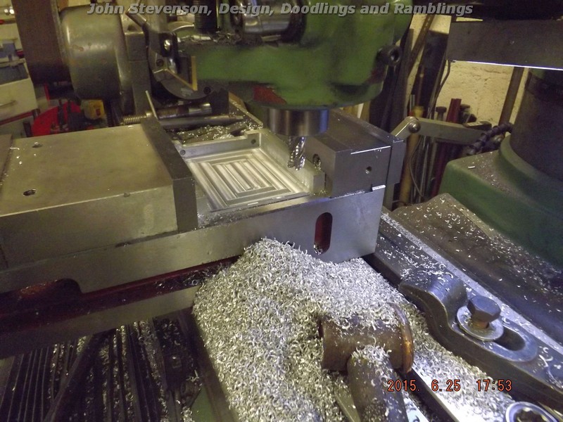
Hunt a bit of 5" x 5" alloy plate out and using precision felt tip marks, pocket the insides out.
The two screw holes line up with two existing holes on the back end of the cross slide so when it's bolted to the slide it forms a nice neat extension.
Scale offered up and it all fits where it touches so job must be a good un?
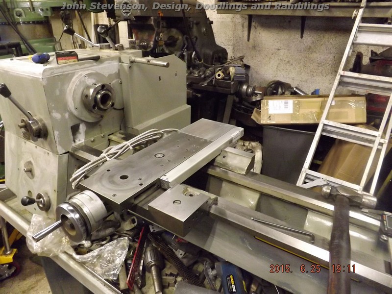
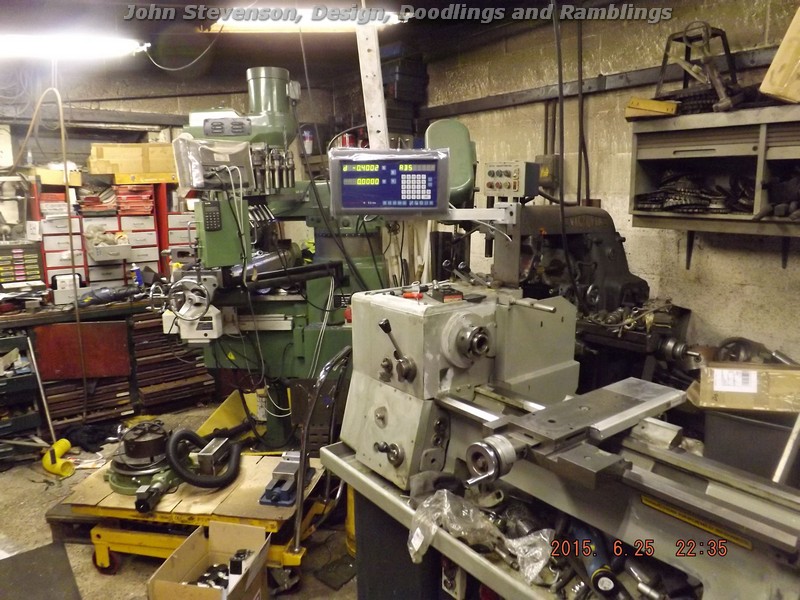
Bracket underneath to take the read head and a bracket on the headstock to take the display arm and display.
Quick test and it's half past dark so that will do me for tonight. Just need the long scale fitting which isn't too bad other than the flat machined surface on the rear is at an angle to the bed so needs some bent plates to carry the read head but that for later. |
| mike mcdermid | 27/06/2015 12:57:52 |
| 97 forum posts | A magnetic strip and read had fits in there, if you machine the extrusion the gibs are clear and the angle bolts for the topslide, I cnc a load of brackets to fit a 30 quid mag strip and 80quid read head, photos can be provided |
| Neil Wyatt | 27/06/2015 14:45:23 |
 19226 forum posts 749 photos 86 articles | Did you use TIG or MIG to weld the scale to the cross slide, John |
| Muzzer | 27/06/2015 16:22:47 |
 2904 forum posts 448 photos | Looks like a neat and robust solution as you might expect! Can't make it out from the photo but is the read head thing hanging down underneath the scale, out the back? What are the height and width of your scales? Never taken my saddle off. I assume you remove the RH leadscrew support, remove the leadscrews, drop the apron (is it simple?) and then remove the saddle retainers. I expect those bolt holes on the cross slide were for the taper turning attachment but hardly a big loss if they were, for me at any rate. Murray |
| John Stevenson | 28/06/2015 13:14:32 |
5068 forum posts 3 photos | Collective answers and questions.
Mike, Never thought about magnetic strips, how do these cope with flood coolant ? Plus I already had this DRO setup. Neil, 2 M4 cap heads supplied with the scale, didn't realise you could TiG weld alloy to cast ?
Murray, I'll get some pics from the back later today and post them. Yes the read head is at the rear and again mounts to two existing 1/4" Whit tapped holes in the carriage. I used a slice sawn off a generic scale bracket left over from fitting another kit.
Saddle comes off easy and just as you say. Bracket off, the two dowels are tapped 2BA for an extractor, screws out, they just pull thru. Apron is secured by 4 cap screws, two front, two rear in the 'top wings ' of the apron and it drops clear. Then the saddle slides off the back and you can upend it to remove the retainers if needed.
Long scale will fit where the taper turning should fit which for me isn't a problem as I never use one, much prefering to use a boring head offset in the tailstock. That should be uneventful except for making a read head bracket that mimics the angle of the bed where the TT should sit.
Next job will be bed wipers. Apparently these are available from the 600 group at around £110 to £120 for the 4 plasticy / rubber bits which in my book is a bit excessive. Toyed with 3D printing the wipers but not sure if there is a suitable filament ? Perhaps someone knows ? Even buying a full spool will be cheaper and some could be sold on.
Alternative is to think outside the box and redesign them taking off the shelf components so any future replacements cost pence. More on this later plus the rear photo's.
Grass cutting and brick laying calls. |
| chris stephens | 28/06/2015 15:13:31 |
| 1049 forum posts 1 photos | Hi John and Neil, Where's the thumbs up button, I want to press it. chriStephens |
| JasonB | 28/06/2015 15:19:44 |
 25215 forum posts 3105 photos 1 articles |
|
| Muzzer | 28/06/2015 17:14:35 |
2904 forum posts 448 photos | Good progress John. Looking forward to seeing more photos once your grass has been cut. I did mine earlier. I made some wipers using that heavy felt that is sold for making furniture feet. About 1/4" thick and self adhesive although the adhesive just looks like double sided tape. Wood chisel and hole punches. It's not really a squeegee type action but you probably don't want that? All the spare tapped holes in my cross slide and saddle have been bunged up with swarf whenever I've looked. What's the clever trick for clearing them without an air line? Murray |
| John Stevenson | 29/06/2015 01:14:58 |
5068 forum posts 3 photos | Ran a 1/4" whit tap thru most of mine to clear the crud out.
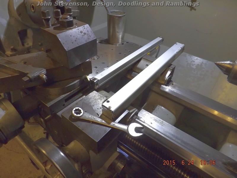
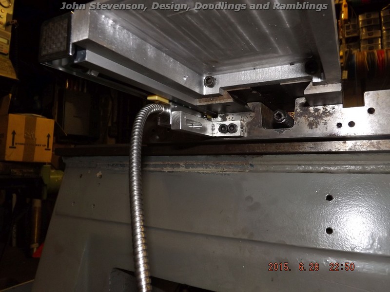
OK pic of the cross slide read head.
Also shows underneath the sub exyension and also not to self that the transit clips, yellow, are still fitted to the scale.
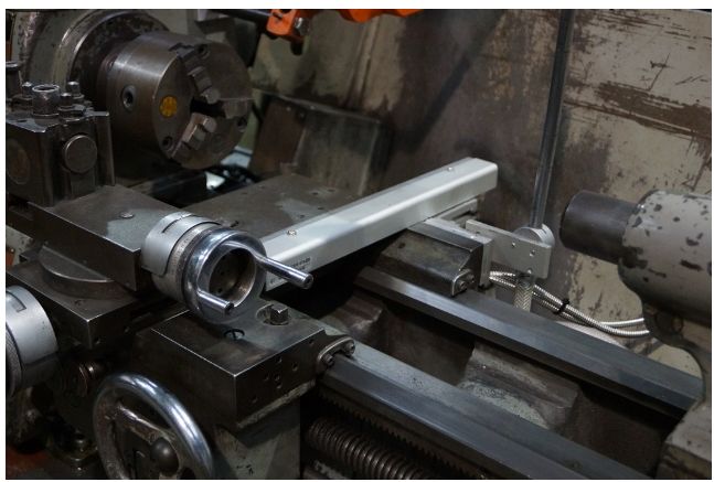
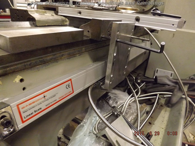
Then I got side tracked and started to fit the long scale. Bolted this to where the taper turning attachment should fit as it already machined flat. For anyone following in these footsteps later the face is at 15 degrees to the vertical
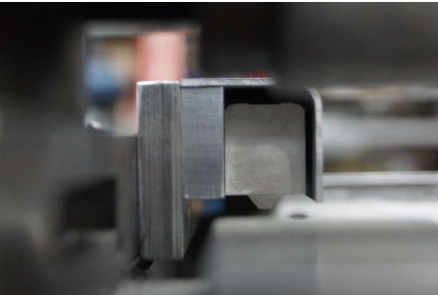
This is one of the generic brackets supplied with the long scales, not that clear but the bottom leg has been shortened and milled away at 15 degrees. Next job is a flat link plate between theis bracket and the long read head.
More to follow at a respectable hour. |
| Douglas Johnston | 29/06/2015 10:10:02 |
 814 forum posts 36 photos | My solution to a similar problem on a small Myford Speed 10 lathe was to fit a magnetic scale underneath the cross slide (photos in my album ) with the read head mounted at the back. This way there is nothing that gets in the way along the side of the cross slide. I did this a while ago and so far it has proved to be very reliable and convenient. If this can be done on a very small lathe with very little space to play with ,it would be a doddle on a larger lathe. Doug |
| John Stevenson | 29/06/2015 11:24:45 |
5068 forum posts 3 photos | Very neat Doug. TBH never though about a magnetic head, for one I had this kit, bought for a machine conversion that was cancelled and I don't know enough about the magnetic strips / heads as regards coolant.
I do know you can build them into a box section which basically mimics a glass scale but running under a cross slide with no protection other than the cross slide I have no experience or knowledge of.
This machine, once the coolant tank is repaired, will be running on neat cutting oil as opposed to soluble as i find it far less work to clean up. In fact as well as a coolant it's also a lubricant that can be left without staining or black marks.
I realise that on your speed 10 you probably don't run coolant other than a spray or brush, which I would do as well, so my concerns won't match yours. I do like to see other variations on a theme, you learn a lot. |
| S.D.L. | 29/06/2015 12:11:12 |
| 236 forum posts 37 photos | Posted by John Stevenson on 29/06/2015 01:14:58:
Ran a 1/4" whit tap thru most of mine to clear the crud out.
Just a note for some who may not be aware, some UK Colchesters are UNC/UNF so there is for example 5 choices for some tapped holes. ie assuming it looks 6mm or 1/4" it could be 1/4BSW 1/4BSF, 1/4UNC 1/4UNF or M6. My MkII student is UNC/UNF other than the bits that I have added that are metric.
Steve |
| John Stevenson | 29/06/2015 14:08:02 |
5068 forum posts 3 photos | Good point Steve. You have now got me thinking. I assumed [ yes we all know the saying ] it was Whit as this machine also has a load of 3/16" on it but checking as not familiar with numbered unified threads there is a #10 at 0.190 x 24 which is only a couple of thou up on 3/13" whit.
So far I haven't found any fine threads on this machine but I'm working at casting level which is ideal for course threads.
A quick check on some non cleaned up holes with a 1/4" whit and 1/4" UNC cap screw and both go in with the same fit. I know they shouldn't because of pitch angle but most screws are very loose on tolerance.
I need to find some fine threads to see the difference. However any extra bolts going into cleaned up tapped holes will be 1/4" whit as I have boxes and boxes of these but only a very few UNC's Tapped holes on the DRO brackets will be metric as the rest of the DRO's are all metric.
[ EDIT ]
Found a large course grub screw that sets the end float on the start / stop shaft 1/2 x 13 so it is a UNC machine. Thanks Steve Edited By John Stevenson on 29/06/2015 15:55:57 |
| Douglas Johnston | 29/06/2015 18:07:50 |
814 forum posts 36 photos | I don't think coolant would be a problem John. The read head is completely sealed as I remember and I covered the magnetic strip with a thin non magnetic layer of brass shimstock. The only problem I can see is a metal chip getting trapped between the read head and the magnetic strip, but this has never happened to me and is quite unlikely due to the fact that these items are pretty well protected due to their location. There is never one perfect solution, just choices to be made. Doug |

Please login to post a reply.
Magazine Locator
Want the latest issue of Model Engineer or Model Engineers' Workshop? Use our magazine locator links to find your nearest stockist!
Sign up to our Newsletter
Sign up to our newsletter and get a free digital issue.
You can unsubscribe at anytime. View our privacy policy at www.mortons.co.uk/privacy
Latest Forum Posts
- *Oct 2023: FORUM MIGRATION TIMELINE*
05/10/2023 07:57:11 - Making ER11 collet chuck
05/10/2023 07:56:24 - What did you do today? 2023
05/10/2023 07:25:01 - Orrery
05/10/2023 06:00:41 - Wera hand-tools
05/10/2023 05:47:07 - New member
05/10/2023 04:40:11 - Problems with external pot on at1 vfd
05/10/2023 00:06:32 - Drain plug
04/10/2023 23:36:17 - digi phase converter for 10 machines.....
04/10/2023 23:13:48 - Winter Storage Of Locomotives
04/10/2023 21:02:11 - More Latest Posts...
- View All Topics
Support Our Partners


Shopping Partners
Subscription Offer

Latest "For Sale" Ads
- Reeves** - Rebuilt Royal Scot by Martin Evans
by John Broughton
£300.00 - BRITANNIA 5" GAUGE James Perrier
by Jon Seabright 1
£2,500.00 - Drill Grinder - for restoration
by Nigel Graham 2
£0.00 - WARCO WM18 MILLING MACHINE
by Alex Chudley
£1,200.00 - MYFORD SUPER 7 LATHE
by Alex Chudley
£2,000.00 - More "For Sale" Ads...
Latest "Wanted" Ads
- D1-3 backplate
by Michael Horley
Price Not Specified - fixed steady for a Colchester bantam mark1 800
by George Jervis
Price Not Specified - lbsc pansy
by JACK SIDEBOTHAM
Price Not Specified - Pratt Burnerd multifit chuck key.
by Tim Riome
Price Not Specified - BANDSAW BLADE WELDER
by HUGH
Price Not Specified - More "Wanted" Ads...
Get In Touch!
Do you want to contact the Model Engineer and Model Engineers' Workshop team?
You can contact us by phone, mail or email about the magazines including becoming a contributor, submitting reader's letters or making queries about articles. You can also get in touch about this website, advertising or other general issues.
Click THIS LINK for full contact details.
For subscription issues please see THIS LINK.
Digital Back Issues


Donate

 Register
 Log-in
Model Engineer Magazine
- Percival Marshall
- M.E. History
- LittleLEC
- M.E. Clock

ME Workshop
- An Adcock
- & Shipley
- Horizontal
- Mill

Subscribe Now
- Great savings
- Delivered to your door

Pre-order your copy!
- Delivered to your doorstep!
- Free UK delivery!
All Forum Topics > Manual machine tools > Lathe design not keeping up