Forum sponsored by:

The Workshop Progress Thread 2019
| Pete White | 11/02/2019 20:19:09 |
| 223 forum posts 16 photos | Engineering porn, Pete |
| mechman48 | 12/02/2019 11:10:06 |
 2947 forum posts 468 photos | Howard; a couple of pics of the cobbler automaton would be nice. |
| Howard Lewis | 14/02/2019 01:45:53 |
| 7227 forum posts 21 photos | Sadly, was so obsessed with sorting it out that took no pictures. Should have, if only to show the damage and bodges, (likely to make matters worse ), previously present. Would guess, from the telephone number on the baseboard, that it was pretty old (020 code) Basically, a geared shaded pole motor drove a multilobe cam. The follower is on a lever which pivots on the left frame. The lever carries three screwed rods, with ball joint ends, which run vertically upwards. The undamaged one nods the head, the two that needed straightening and adjusting operate the right arm, wielding the hammer, and the outer one, a bell crank which drives a horizontal rod at shoulder level, which causes the left hand to sweep to and fro across the shoe on the "anvil". The fact that the two rods had been bent in compression implied some fairly large forces, (hence the original motor ran, but did not drive the output shaft ). The cam had been fitted inside out, making the grubscrews inaccessible, which explained why it was loose on the shaft! When fitted with the hub outwards, the cam was running out. It was secured to an arbor, in the lathe and checked with a DTI. The DTi was moved away to allow gentle persuasion, or levering, at appropriate points, until it ran reasonably true again, (1mm+ reduced to less than 0.2mm ) At least the cam now stayed in the groove in the ball bearing follower. Having dispensed with the pack of washers, a solid spacer was turned up to align the follower with the cam. Adjusting the rods took time, because to make any adjustment meant removing a ball joint, giving it one turn and refitting, before checking the effect of the adjustment. Once operating satisfactorily, the back was fitted; which promptly stalled the motor! The ball joint on the outer rod fouled. The rod was refitted with the ball joints inboard, but a foul still remained. This was cleared by drilliing a hole in the plastic back, and steadily carving bits away, to extend it, until the foul cleared. From its state, the shirt was even older than the ones that i wear in the workshop; and that's saying something! The new owners seemed impressed with my description of the "as received" condition, the repairs,and the "after" operation, that they gave a bigger donation to Club funds than I had expected. So everyone was happy! Howard |
| duncan webster | 21/03/2019 15:48:58 |
| 5307 forum posts 83 photos | Not my idea, Mr Tredenick from Australia, as featured in MEW Feb 19. How to stop the jaw lifting on your Record drilling vice. Only took an hour or so
Edited By duncan webster on 21/03/2019 15:50:36 |
| Jim Nic | 03/04/2019 22:46:43 |
 406 forum posts 235 photos | In my last post on the progress of Stew Hart's Overcrank design I had made the valve eccentrics (and the eccentric straps) which had to be fitted to the crankshaft centre section before assembling the shaft. I then thought that making up the shaft would naturally be the next operation. When I came to cut the 12mm dia bar to length for the main part I found that the exact length depended on the width of the flywheel and the output pulley hubs. Sooo the next task was to obtain a flywheel casting from Stuart Models and machine it and make a pulley and, while I was at it, a pulley for the governer belt.
Then I assembled the crankshaft using my usual Loctite method but since this was a twin cylinder engine I also pinned the webs. The pins are fitted through the webs from one end, go through both the "big end" and the shaft section but stop short of protruding from the other end of the web.
And here is an assembly shot of the crankshaft in position before I had cut out the redundant pieces between the webs.
Next up I get to fit the laser cut crank return rods
Jim
|
| JasonB | 22/04/2019 13:20:01 |
 25215 forum posts 3105 photos 1 articles | had a try at getting the I F Allman engine going over the weekend and it's nearly there. A few fine tweaks to the gas flow to the actual engine and the position of the burner to get the timing spot on should have it firing a bit more often which should result in some longer runs. |
| Ian Skeldon 2 | 22/04/2019 15:56:08 |
| 543 forum posts 54 photos | Duncan Thanks for the tip, will give that a go. Jason I love that engine, just to give an idea of the size, what diameter is the fly wheel? |
| JasonB | 22/04/2019 16:23:58 |
25215 forum posts 3105 photos 1 articles | 10.5" dia and very heavy due to the thick section rim. |
| Ian Skeldon 2 | 22/04/2019 20:08:29 |
| 543 forum posts 54 photos | But what a beauty she is, nice one Jason. |
| duncan webster | 23/04/2019 12:28:53 |
| 5307 forum posts 83 photos | Getting ready for a repetition job, thought a rear toolpost for my little lathe might help, so here it is, not quite finished, needs another tee nut making to hold it down, but grand dad duties call. |
| john carruthers | 30/04/2019 08:44:53 |
 617 forum posts 180 photos | The new shed/workshop is finally erected, I've been aiming for a better set up since we got here last October. |
| JasonB | 05/05/2019 12:24:10 |
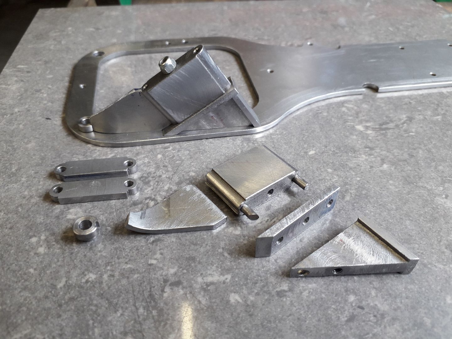
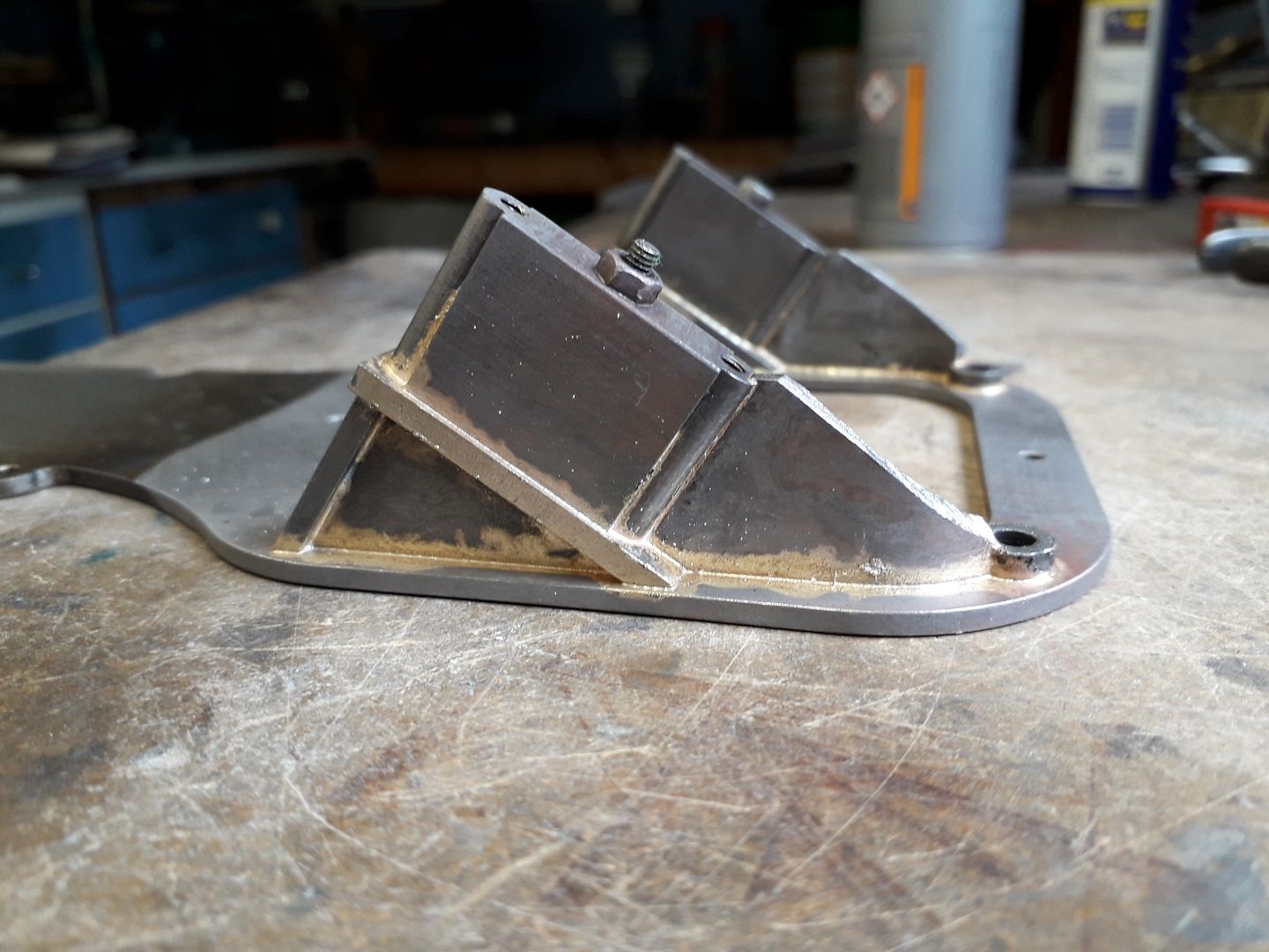
25215 forum posts 3105 photos 1 articles | I've been machining up a few more bits for the mill engine I posted in the KX-3 thread that will make up the bearing housings.
Then heated them up with a bit of flux and silver solder thrown in for good measure
And after a 40 min soak in brick cleaner the solder looks to have flowed OK. Just need to file the two curved webs to shape now.
|
| Roderick Jenkins | 07/05/2019 15:47:42 |
 2376 forum posts 800 photos | Machined the cylinder for my (air-cooled) Farm Boy hit n miss
Rod |
| JasonB | 07/05/2019 16:25:55 |
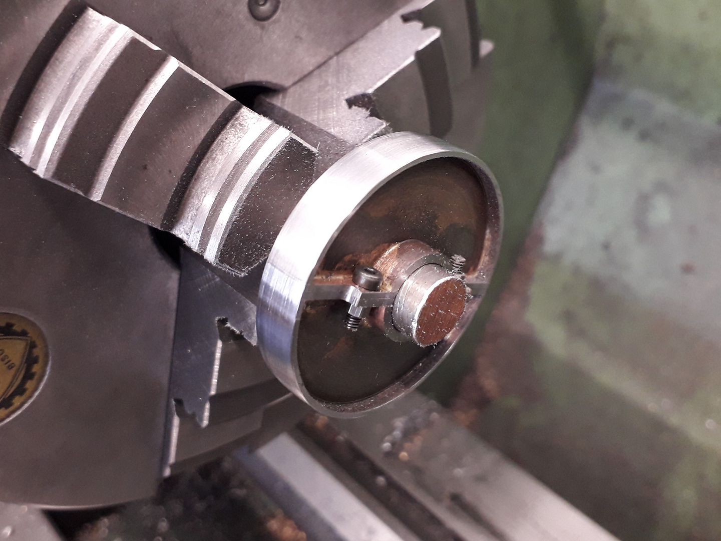
25215 forum posts 3105 photos 1 articles | Yesterday i made a split pulley to drive the mill engine's governor, was happy that it held on the 10mm PGMS shaft for final turning and crowning of the face. 40mm OD and M2 temporary fixings, just a bit of filing to round off the flange around the bolts to do.
|
| Roy Garden | 14/05/2019 20:03:06 |
 23 forum posts 9 photos | Well, after posting in my Intro that I'm starting with a mill and will get to a lathe as time / finances / swmbo allows, With new toys in garage just mocking me for my limited abilities (I've worked with hi tech machined tools all my working life in the oilfield and never knew how little I knew 'till I started to bodge bits of metal myself) Knobs (the bronze thingies) they are used to pull a recessed nut out to allow wing extensions to engage on the glider. |
| JasonB | 27/05/2019 16:13:08 |
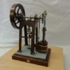
25215 forum posts 3105 photos 1 articles | Finally admitted defeat at being able to get my Forest based engine to run as a flame licker. I had always thought that if it would not run that I could convert it to a poppet valve engine much like the Jowitt I made a few years ago. In the end I decided on a cam and follower operated spool valve as I had not made an engine with a spool valve before. Still needs a tidy up and the plumbing sorted out but seems to run at a nice steady pace. Sorry about the few seconds of compressor noise at about 40 secs in. |
| Neil Wyatt | 27/05/2019 18:57:16 |
 19226 forum posts 749 photos 86 articles | Posted by mechman48 on 12/02/2019 11:10:06:
Howard; a couple of pics of the cobbler automaton would be nice. I remember one from when I was a boy. He looked like a bearded Magwitch. Neil |
| GoCreate | 29/05/2019 10:41:04 |
 387 forum posts 119 photos | Started a new project, 5"g Lion. These are the boiler parts ready for the dreaded silver soldering, I'm tackling the boiler first as that is the biggest challenge for me, if I can achieve this then I can finish the engine. I'm generally following the LBSC drawings but using photo's I took of the full size engine in the Liverpool City museum to add detail.
Nigel |
| duncan webster | 29/05/2019 15:23:00 |
| 5307 forum posts 83 photos | I have a vague recollection (and it's no more than that) that there is a problem with the LBSC design valve gear for Lion. If I were you I'd contact OLCO who have a list of errors and hopefully solutions |
| GoCreate | 30/05/2019 08:47:24 |
387 forum posts 119 photos | Thanks Duncan. Your recollection is correct, I have an ME article 21st Dec 1973 that gives corrections to the 5"g valve gear. Nigel |
.jpg")
.jpg")


.jpg")


This thread is closed.
Magazine Locator
Want the latest issue of Model Engineer or Model Engineers' Workshop? Use our magazine locator links to find your nearest stockist!
Sign up to our Newsletter
Sign up to our newsletter and get a free digital issue.
You can unsubscribe at anytime. View our privacy policy at www.mortons.co.uk/privacy
Latest Forum Posts
- *Oct 2023: FORUM MIGRATION TIMELINE*
05/10/2023 07:57:11 - Making ER11 collet chuck
05/10/2023 07:56:24 - What did you do today? 2023
05/10/2023 07:25:01 - Orrery
05/10/2023 06:00:41 - Wera hand-tools
05/10/2023 05:47:07 - New member
05/10/2023 04:40:11 - Problems with external pot on at1 vfd
05/10/2023 00:06:32 - Drain plug
04/10/2023 23:36:17 - digi phase converter for 10 machines.....
04/10/2023 23:13:48 - Winter Storage Of Locomotives
04/10/2023 21:02:11 - More Latest Posts...
- View All Topics
Support Our Partners


Shopping Partners
Subscription Offer

Latest "For Sale" Ads
- Reeves** - Rebuilt Royal Scot by Martin Evans
by John Broughton
£300.00 - BRITANNIA 5" GAUGE James Perrier
by Jon Seabright 1
£2,500.00 - Drill Grinder - for restoration
by Nigel Graham 2
£0.00 - WARCO WM18 MILLING MACHINE
by Alex Chudley
£1,200.00 - MYFORD SUPER 7 LATHE
by Alex Chudley
£2,000.00 - More "For Sale" Ads...
Latest "Wanted" Ads
- D1-3 backplate
by Michael Horley
Price Not Specified - fixed steady for a Colchester bantam mark1 800
by George Jervis
Price Not Specified - lbsc pansy
by JACK SIDEBOTHAM
Price Not Specified - Pratt Burnerd multifit chuck key.
by Tim Riome
Price Not Specified - BANDSAW BLADE WELDER
by HUGH
Price Not Specified - More "Wanted" Ads...
Get In Touch!
Do you want to contact the Model Engineer and Model Engineers' Workshop team?
You can contact us by phone, mail or email about the magazines including becoming a contributor, submitting reader's letters or making queries about articles. You can also get in touch about this website, advertising or other general issues.
Click THIS LINK for full contact details.
For subscription issues please see THIS LINK.
Digital Back Issues


Donate

 Register
 Log-in
Model Engineer Magazine
- Percival Marshall
- M.E. History
- LittleLEC
- M.E. Clock

ME Workshop
- An Adcock
- & Shipley
- Horizontal
- Mill

Subscribe Now
- Great savings
- Delivered to your door

Pre-order your copy!
- Delivered to your doorstep!
- Free UK delivery!
All Forum Topics > Work In Progress and completed items > The Workshop Progress Thread 2019