Forum sponsored by:

No 4407 More Errors
| Nicholas Farr | 02/07/2011 12:40:34 |
 3988 forum posts 1799 photos | Hi Kwil, touché. I think one needs to read the text as well as look at the drawings, eg. with the items that are silver soldered on to the water jacket in the Rider Ericsson article, the author states that the really critical item to be positioned is the bearing mounting bracket, the two slightly different dimensions given for the crank bracket pad being insignificant to my mind.
Regards Nick. Edited By Nicholas Farr on 02/07/2011 13:03:21 |
| Ian S C | 02/07/2011 12:48:10 |
 7468 forum posts 230 photos | I might have a go at the Rider Ericsson, But the dimentions will be no trouble, I'll use my usual method, the drawing gives the general outline, and away I go. If I do build, I will change the cylinder from brass to steel, or cast iron to reduce friction. It looks a nice simple build. Ian S C |
| JasonB | 02/07/2011 13:40:07 |
 25215 forum posts 3105 photos 1 articles | I too doubt that I will make one, if I did then the pivot for the flywheel would be moved as it hangs out beyond the upright on the full size, having it directly over the upright makes the who engine too long. I would also make all the bits that solder onto the jacket oversize and once soldered machine the faces & tap the holes, far more likely to get it all lined up with the bore that way, in effect treating it as a casting.
As I said earlier the more experianced of us can likely work out what is supposed to be there but I get quite a few PMs from the those that are new to the hobby asking about things like this as they don't want to look silly asking something that may be obvious to us. So rather than be selfish and "going to make some swarf" I point these things out in the hope it will help others.
Now we just need answers for the Great Western
J |
| Bill Pudney | 03/07/2011 03:55:15 |
| 622 forum posts 24 photos | My better half told me that pedantry is dead. This thread proves her wrong. cheers Bill Pudney |
| KWIL | 03/07/2011 09:54:19 |
| 3681 forum posts 70 photos | Long may it live!! |
| Doubletop | 03/07/2011 10:43:03 |
 439 forum posts 4 photos | When I saw "... he lives in Greece" I cracked up, but at least it was a new one that wasn’t in Jeff Daymans list. “Greek tragedy” and “its all Greek to me” also came to mind. Seriously; having recently been a victim of this drawing errors problem I was coming to the conclusion that there was an issue in the illustration area, now I believe it to be deeper than that and more of a systemic problem in the way ME is produced. I’m new to this area of engineering but I’d have expected the discipline of getting drawings right would have been second nature to people who’d been in the industry for years. I’d also have thought that these days this sort of problem would be reduced by the use of computers. So rather than vilifying David and the crew is there anything that can be suggested that would be useful to them to improve the magazine quality? A review of the process? Or even a group that could assist David with proofing the articles before they are printed. They pay the original author, so of course for a fee. Pete PS: publishing the corrections here isn’t that helpful either as I doubt every ME reader trolls through this site just in case they find a correction. All of the above needs to be consolidated into a “Corrections” item in the magazine. Give the regularity of these issues maybe it should be a regular feature. |
| Versaboss | 03/07/2011 14:33:15 |
| 512 forum posts 77 photos | I cannot help but draw your attention to 'another one' which escaped the critical eyes up to now. On page 39 there is an article about making a chuck adaptor plate for the Hobbymat lathe. The text in the article gives the following data: Hobbymat spindle flange diameter: 55 mm Chuck internal register diameter: 56 mm The drawing clearly shows a boss (for the chuck) of 55 mm diameter, and on the other side a recess (for the spindle flange) of 56 mm diameter.
If someone would produce such an adaptor, trusting and relying upon the drawing only, he would be up for a nice surprise... Not the end of the world I admit, but a sign of the quality checks done (or not). Greetings, Hansrudolf |
| JasonB | 03/07/2011 15:30:32 |
25215 forum posts 3105 photos 1 articles | Well I had to leave one for somebody else to find
 And lets face it if you are not too pedantic about the concentricity of the chuck it will all fit (loosly) together that way
 J Edited By JasonB on 03/07/2011 15:32:08 |
| Nicholas Farr | 03/07/2011 15:48:48 |
3988 forum posts 1799 photos | Hi, well I have just checked my Hobbymat, and the register on the lathe comes out at 55.9mm, so it is possible that the drawing is correct and the text is wrong. It would pay anyone who will be making such an adapter to measure their own registers on the lathe and any new chuck they use anyway. Then follow the procedure given in the article.
Regards Nick. |
| JasonB | 03/07/2011 15:57:52 |
25215 forum posts 3105 photos 1 articles | Hobbymat was made with 3 different spindle sizes - 55, 56 and 63mm Text and drawing would seem to be based on a 55mm machine
Anyway the drawing would still be wrong as it shows 55mm into the 56mm chuck.
J Edited By JasonB on 03/07/2011 15:59:02 |
| JasonB | 03/07/2011 16:17:27 |
25215 forum posts 3105 photos 1 articles | Is it a clock making thing or is there another reason that the OD of all the gearwheels in the clock article seem to be 10-20 thou over size using (teeth +2) *MOD?
Or is that why clock makers use a depthing tool rather than measure out the gear centres
 J Edited By JasonB on 03/07/2011 16:19:36 |
| JasonB | 03/07/2011 17:00:55 |
25215 forum posts 3105 photos 1 articles | On no I should have kept quiet about the clock. Thought I better read the text from the previous installment incase something was hidden in the text. We have , a 36tooth gear 3 times the dia of a 39T gear and again OD that are plus or minus 20thou.
Seems complacancy is more predominant than pedancy
J Edited By JasonB on 03/07/2011 17:07:08 |
| ady | 04/07/2011 04:10:45 |
| 612 forum posts 50 photos | I don't see what the problem is. Everything fits together perfectly if you adapt the build as it progresses Edited By ady on 04/07/2011 04:11:39 |
| Phil P | 04/07/2011 08:16:20 |
| 851 forum posts 206 photos | Posted by JasonB on 03/07/2011 16:17:27:
Is it a clock making thing or is there another reason that the OD of all the gearwheels in the clock article seem to be 10-20 thou over size using (teeth +2) *MOD?
Or is that why clock makers use a depthing tool rather than measure out the gear centres
J
Edited By JasonB on 03/07/2011 16:19:36 Jason According to the clock wheel and pinion cutting book by J.M. Wild :-
For wheels the OD is (N + 2.76) x Module
For pinions of 6,7 & 8 teeth the OD is (N + 1.71) x Module
For pinions of 10,12 & 16 teeth the OD is (N + 1.61) x Module
That is assuming the tooth form to be cycloidal as opposed to involute.
Phil
|
| JasonB | 04/07/2011 17:00:01 |
25215 forum posts 3105 photos 1 articles | Thanks for that Phil, comes out OK using that formula, learn something new every day.
Jason |
| JasonB | 09/07/2011 14:03:29 |
25215 forum posts 3105 photos 1 articles | Posted by David Clark 1 on 01/07/2011 08:52:16:
Fig 10
The 2.85mm hole centerline is not shown in line with the 1.75mm recess, it is clearly shown above it. Therefore we either need a height for the hole (PROBABLY 2MM) or the 1.75mm is not the size of the notches on the bearing blocks.
On the original it is clearly shown in line with the 1.75 steps.
Having just seen this engine in the flesh today at Guildford I can confirm thet the holes are above the 1.75mm step.
The engine was running very sweetly so I would suggest to anyone thinking of making this not to be put off by these drawing issues if they can all be resolved it will build into a nice piece to add to your collection
Jason
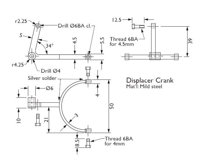
PS Drawings in 4408 look beter just need the angle for teh displacer crank in Fig 23 its shown as a strange 34+ |
| David Clark 1 | 09/07/2011 14:44:16 |
 3357 forum posts 112 photos 10 articles | Hi There
This is the drawing I aproved for press.
As you can see it clearly says 34 degrees.
It has obviously been changed by the page design software.
I will get this checked on Monday.
Probably to do with the fonts used.
regards David
 Edited By David Clark 1 on 09/07/2011 14:44:55 |
| JasonB | 09/07/2011 15:29:37 |
25215 forum posts 3105 photos 1 articles | Yes could well have scanned in 84 and got 34 out.
Thanks, J |
| blowlamp | 09/07/2011 15:39:28 |
 1885 forum posts 111 photos | I get that angle at 77 degrees by tracing over it.
Martin. |
| JasonB | 09/07/2011 16:16:40 |
25215 forum posts 3105 photos 1 articles | Looks like it could also do with a dimension between the fork holes and the 4mm hole while you are at it David, as yw long teh lower arm should be without a lot of calculation |
Please login to post a reply.
Magazine Locator
Want the latest issue of Model Engineer or Model Engineers' Workshop? Use our magazine locator links to find your nearest stockist!
Sign up to our Newsletter
Sign up to our newsletter and get a free digital issue.
You can unsubscribe at anytime. View our privacy policy at www.mortons.co.uk/privacy
Latest Forum Posts
- hemingway ball turner
04/07/2025 14:40:26 - *Oct 2023: FORUM MIGRATION TIMELINE*
05/10/2023 07:57:11 - Making ER11 collet chuck
05/10/2023 07:56:24 - What did you do today? 2023
05/10/2023 07:25:01 - Orrery
05/10/2023 06:00:41 - Wera hand-tools
05/10/2023 05:47:07 - New member
05/10/2023 04:40:11 - Problems with external pot on at1 vfd
05/10/2023 00:06:32 - Drain plug
04/10/2023 23:36:17 - digi phase converter for 10 machines.....
04/10/2023 23:13:48 - More Latest Posts...
- View All Topics
Support Our Partners


Shopping Partners
Subscription Offer

Latest "For Sale" Ads
- Reeves** - Rebuilt Royal Scot by Martin Evans
by John Broughton
£300.00 - BRITANNIA 5" GAUGE James Perrier
by Jon Seabright 1
£2,500.00 - Drill Grinder - for restoration
by Nigel Graham 2
£0.00 - WARCO WM18 MILLING MACHINE
by Alex Chudley
£1,200.00 - MYFORD SUPER 7 LATHE
by Alex Chudley
£2,000.00 - More "For Sale" Ads...
Latest "Wanted" Ads
- D1-3 backplate
by Michael Horley
Price Not Specified - fixed steady for a Colchester bantam mark1 800
by George Jervis
Price Not Specified - lbsc pansy
by JACK SIDEBOTHAM
Price Not Specified - Pratt Burnerd multifit chuck key.
by Tim Riome
Price Not Specified - BANDSAW BLADE WELDER
by HUGH
Price Not Specified - More "Wanted" Ads...
Get In Touch!
Do you want to contact the Model Engineer and Model Engineers' Workshop team?
You can contact us by phone, mail or email about the magazines including becoming a contributor, submitting reader's letters or making queries about articles. You can also get in touch about this website, advertising or other general issues.
Click THIS LINK for full contact details.
For subscription issues please see THIS LINK.
Digital Back Issues


Donate

 Register
 Log-in
Model Engineer Magazine
- Percival Marshall
- M.E. History
- LittleLEC
- M.E. Clock

ME Workshop
- An Adcock
- & Shipley
- Horizontal
- Mill

Subscribe Now
- Great savings
- Delivered to your door

Pre-order your copy!
- Delivered to your doorstep!
- Free UK delivery!
All Forum Topics > Drawing Errors and Corrections > No 4407 More Errors