Forum sponsored by:

The Workshop Progress thread 2022
| Pete. | 10/05/2022 17:40:55 |
 910 forum posts 303 photos | Nearly finished restoration of my BNL no5 Arbor Press, while taking it apart the hand wheel broke, I tried pulling it off with a 3 leg puller but it snapped, it was spinning around freely on the Arbor but just would not come off, I ended up slitting it with a hacksaw then chain drilling it to remove a section so it would come off the Arbor. After getting it off the problem became apparent, over time it must have been slipping and repeatedly got spun round causing the Arbor to mushroom out either side of the screw, and wear 2 grooves into the inside of the bore making it mechanically impossible to remove. So decided to give mig bronze brazing a try as I've never done it, I was hoping this method would remove the need for pre heat and post heat, the repair below was done with no pre or post heat. It's a bit tricky and definitely doesn't produce nice weld beads like Tig, but after a bit of fettling with the die grinder and a carbide burr, it's hard to notice where it was brazed anyway.
Edited By Pete. on 10/05/2022 17:44:17 |
| Pete. | 18/05/2022 21:10:19 |
910 forum posts 303 photos | Some more cast iron repairs, I am happy to say the mig brazing process can repair cast iron reliably with no pre or post heat and no cracking, it's not pretty but it is quite easy and hassle free, 10 minutes with the die grinder and job done.
|
| Hopper | 18/05/2022 22:25:23 |
 7881 forum posts 397 photos | Wow that looks like the way to fix cast iron. I never knew you could do that with a MIG. Thanks for the tip. |
| Buffer | 19/05/2022 09:31:06 |
| 430 forum posts 171 photos | Pete that's a great job, what was the wire you used? Thanks
|
| Andy Chancer | 19/05/2022 12:29:46 |
| 27 forum posts | Nice job there. Edited By Andy Chancer on 19/05/2022 12:30:20 |
| Jon Lawes | 19/05/2022 14:52:21 |
 1078 forum posts | Excellent work, thanks for the information. |
| Mark Rand | 19/05/2022 20:35:14 |
| 1505 forum posts 56 photos | I scrounged a large reel of Inconel 82 when they were having a clearout of the Weld Lab at work. It's wonderful stuff for 'stick anything to anything' welding. I've successfully used it for Cast iron and stainless repairs. |
| Pete. | 19/05/2022 22:18:51 |
910 forum posts 303 photos | Posted by Buffer on 19/05/2022 09:31:06:
Pete that's a great job, what was the wire you used? Thanks
Hi, the wire used is SIF no8 bronze mig wire, bought from R-tech welding, it is used with pure Argon gas, and aluminium torch tips with a Teflon liner in the torch. This is recommended as a bearing surface so could be useful for building up worn areas and then machining. The liner was about 11 quid on ebay, the wire was 30 something plus post for a 0.8kg reel, not cheap but should get a good few repairs out of it. I'm not familiar with inconel 82 brazing wire, all I know is it's an extremely expensive material, never seen it for sale anywhere. |
| Pete. | 20/05/2022 23:41:20 |
910 forum posts 303 photos | Finished for now, a few little bits to do when time allows, replace the hex head screws clamping the support legs with hand knobs for convenience, and need to make crank handle for the table lowering and raising, but it's usable now.
|
| Baz | 21/05/2022 08:39:34 |
| 1033 forum posts 2 photos | Wow! That is an excellent piece of kit you’ve got there Pete. |
| Jim Nic | 11/06/2022 21:31:00 |
 406 forum posts 235 photos | Having completed the Norden engine and cleaned the workshop I was at a bit of a loss looking for an interesting follow up. Scrolling through the Mad Modder site I came upon the very thing, a 3 cylinder radial single acting engine. Originally designed, I believe, by Edgar Westbury as the Cygnet Royal and subsequently simpified by Elmer Verburg. This version is an amalgam of both designers thoughts put together by Stew Hart. This is Stew's engine and what I am aiming for.
To kick off I took a piece of aluminium bar:
And removed most of the metal from it until I was left with this:
For scale the flats on the hexagon are 25.4mm wide. The next opportunity for me to make a mistake is the 3 cylinders and their cast iron liners. Wish me luck. Jim
Edited By Jim Nic on 11/06/2022 21:34:33 |
| Jim Nic | 14/07/2022 15:43:27 |
406 forum posts 235 photos | Well, it's only taken me a month or so but some progress has been made. The cylinders as drawn are made as a 1 piece aluminium tube with squared ends and a cast iron liner. Looking at materials I had to hand I made mine as the ali tube, separate end flanges and the cast iron liner:
Since my engine will only ever run on air the parts were assembled using Loctite 638 which I have very confidence will hold.
Next will be the cylinder heads, which are straight forward, and the crankcase breather then I can look at the crankshaft and its housing. Jim
Edited By Jim Nic on 14/07/2022 15:44:30 |
| Anthony Knights | 25/09/2022 12:07:26 |
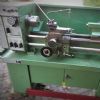
| 681 forum posts 260 photos | I recently finished converting my lathe to a 3 phase inverter/ motor drive. I've had had no luck finding a suitable enclosure for the inverter. Those that are deep enough are far too big in height and width. I had a dig round in my old installation gear and found a pair of boxes about right for height and width, but not deep enough.
Measurement showed that stacking the boxes on top of each other would give sufficient depth. So, onto the mini mill and remove the back from one box. I did it this way because I'm hopeless at cutting straight lines with a handsaw. I also machined off any sticky-up bits to give a flat surface.
Using plastic rods in the corner holes for location and strength, the boxes were glued together and when set, undercoated and then sprayed black
Fitted the inverter on the box's metal back plate and fitted it in the box. It looks off-centre in the photo but that's down to the camera angle.
I then tried the lid which was already prepared with a window cut for the inverter display and then sprayed. The piece of Perspex for the window is at the bottom of the picture and just needs gluing in.
I now have to fit the cable glands, wire it up (again) and fit it on the wall. That's the easy bit. I then have to decipher the programming instructions which came on a CD with a 301 page PDF document. It did come pre-programmed, but I need to increase the maximum frequency (currently set at 50Hz), so I can get the full range of speeds on the lathe. Hopefully that will be relatively easy to do. |
| Anthony Knights | 25/09/2022 13:09:11 |
| 681 forum posts 260 photos | Now all connected up and fixed on the wall. Working, but still got to tackle the programming bit.
|
| Philip Rowe | 25/09/2022 13:32:33 |
| 248 forum posts 33 photos | I like that idea, very intuitive. I know I wouldn't have thought of using two boxes, instead probably wasting hours of time trawling the net looking for something that doesn't exist! Phil |
| JasonB | 17/10/2022 16:45:51 |
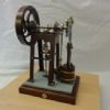
 25215 forum posts 3105 photos 1 articles | The latest replica of a small steam engine turned it's flywheel for the first time yesterday, this time its of a Donkey Pump sold by Bassett Lowke (not sure if they made them) I've saved the photos of a few that have been on e-bay over the last few years and there is one there now. More details and a better video when it's had a lick of paint and the pump valve chamber is made.  |
| Michael Gilligan | 17/10/2022 16:50:54 |
 23121 forum posts 1360 photos | Looks good, Sounds good … I like it MichaelG. |
| JasonB | 13/11/2022 16:59:03 |
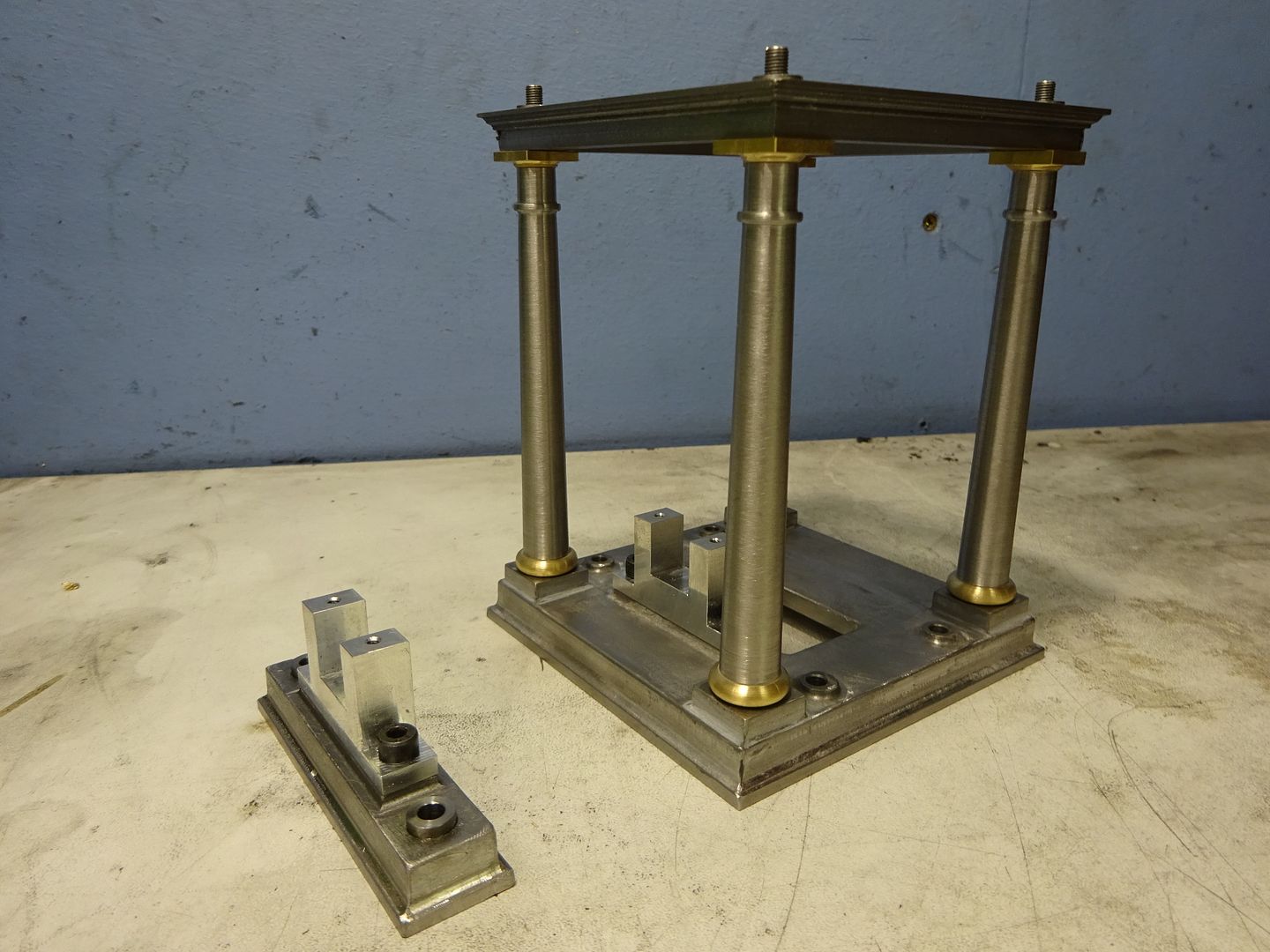
25215 forum posts 3105 photos 1 articles | It's a james Coombes but not as you know it!
Having reworked the Stuart Real recently I thought that the James Coombes could do with similar treatment. To my eye this looks better than the two flat 3/16" plates and very plain columns of the original model |
| JasonB | 25/11/2022 19:35:00 |
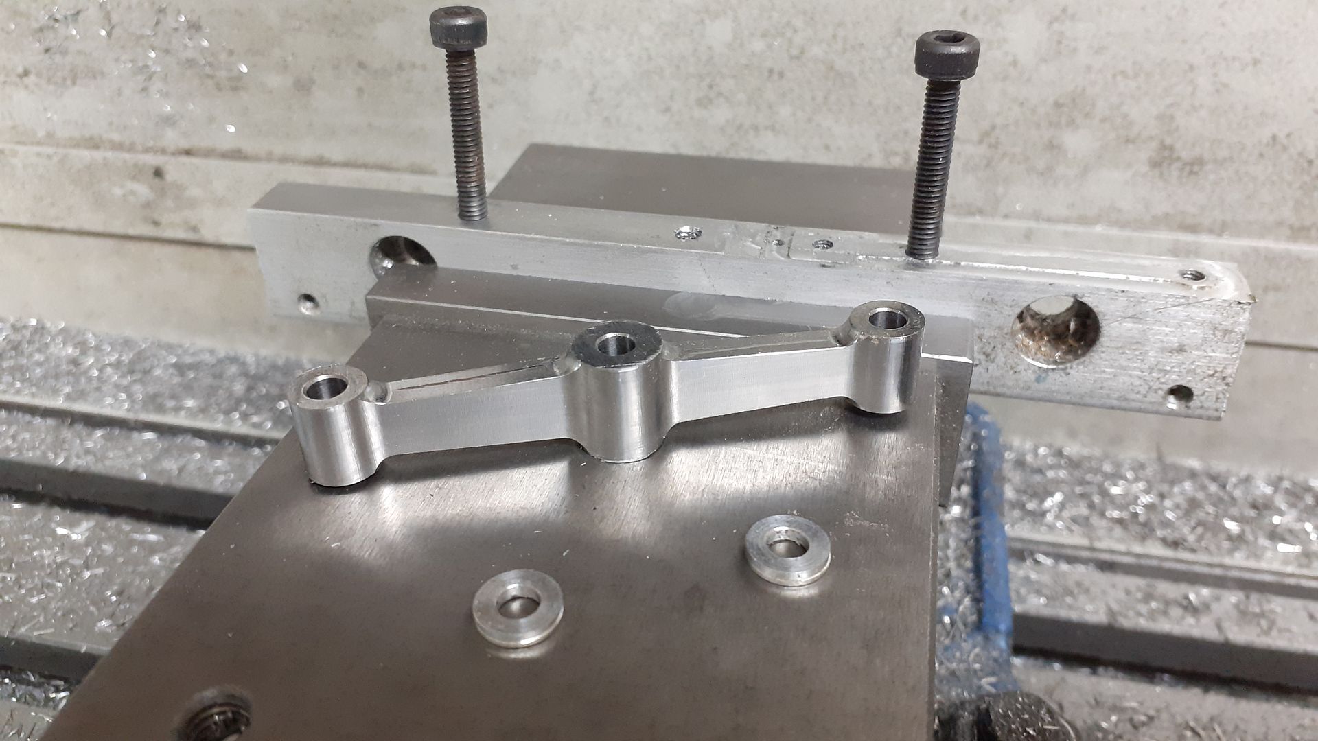
25215 forum posts 3105 photos 1 articles | having done the CAM during the week I popped out to the work shop this evening and got the KX-3 to knock this out from a 70mm length of 12mm x 1/2" steel that had been previously drilled and reamed on the manual mill.
|
| Oldiron | 26/11/2022 10:46:27 |
| 1193 forum posts 59 photos | @Anthony Knights. I have used inverters for many years at home & in industry and not one has been in an enclosure. They generate quite a lot of heat when working and this needs to be dissipated. I see no vents in your enclosure. I have 2 in my workshop mounted on the wall above & to the side of the machines they feed. Both have remote pendants on the machines. They are mounted 25mm off of the surface with at least 50mm of clearance around the sides as reommended in the installation instructions. Been on the wall and in regular use for several years without any problems. Hopefully you will have no ventilation problems. Your use of 2 boxes to make one is a great solution. regards |


This thread is closed.
Magazine Locator
Want the latest issue of Model Engineer or Model Engineers' Workshop? Use our magazine locator links to find your nearest stockist!
Sign up to our Newsletter
Sign up to our newsletter and get a free digital issue.
You can unsubscribe at anytime. View our privacy policy at www.mortons.co.uk/privacy
Latest Forum Posts
- hemingway ball turner
04/07/2025 14:40:26 - *Oct 2023: FORUM MIGRATION TIMELINE*
05/10/2023 07:57:11 - Making ER11 collet chuck
05/10/2023 07:56:24 - What did you do today? 2023
05/10/2023 07:25:01 - Orrery
05/10/2023 06:00:41 - Wera hand-tools
05/10/2023 05:47:07 - New member
05/10/2023 04:40:11 - Problems with external pot on at1 vfd
05/10/2023 00:06:32 - Drain plug
04/10/2023 23:36:17 - digi phase converter for 10 machines.....
04/10/2023 23:13:48 - More Latest Posts...
- View All Topics
Support Our Partners


Shopping Partners
Subscription Offer

Latest "For Sale" Ads
- Reeves** - Rebuilt Royal Scot by Martin Evans
by John Broughton
£300.00 - BRITANNIA 5" GAUGE James Perrier
by Jon Seabright 1
£2,500.00 - Drill Grinder - for restoration
by Nigel Graham 2
£0.00 - WARCO WM18 MILLING MACHINE
by Alex Chudley
£1,200.00 - MYFORD SUPER 7 LATHE
by Alex Chudley
£2,000.00 - More "For Sale" Ads...
Latest "Wanted" Ads
- D1-3 backplate
by Michael Horley
Price Not Specified - fixed steady for a Colchester bantam mark1 800
by George Jervis
Price Not Specified - lbsc pansy
by JACK SIDEBOTHAM
Price Not Specified - Pratt Burnerd multifit chuck key.
by Tim Riome
Price Not Specified - BANDSAW BLADE WELDER
by HUGH
Price Not Specified - More "Wanted" Ads...
Get In Touch!
Do you want to contact the Model Engineer and Model Engineers' Workshop team?
You can contact us by phone, mail or email about the magazines including becoming a contributor, submitting reader's letters or making queries about articles. You can also get in touch about this website, advertising or other general issues.
Click THIS LINK for full contact details.
For subscription issues please see THIS LINK.
Digital Back Issues


Donate

 Register
 Log-in
Model Engineer Magazine
- Percival Marshall
- M.E. History
- LittleLEC
- M.E. Clock

ME Workshop
- An Adcock
- & Shipley
- Horizontal
- Mill

Subscribe Now
- Great savings
- Delivered to your door

Pre-order your copy!
- Delivered to your doorstep!
- Free UK delivery!
All Forum Topics > Work In Progress and completed items > The Workshop Progress thread 2022