Forum sponsored by:

08 shunter quartering
dan jeavons shunter how to quarter
| Dave Owen | 28/02/2014 10:57:52 |
| 29 forum posts 2 photos | Hi does any body know the best way to quarter the cranks on a 5 inch gauge jeavons 08 shunter, the cranks are outside the frames and it is only the cranks that need to be quartered and not the wheels as they are inside the frames. many thanks in advance D |
| IanT | 28/02/2014 11:45:21 |
| 2147 forum posts 222 photos | Hi Dave, There are quite a few ways to do this and many have been suggested over the years, some involving jigs and others lathe set-ups (needs the axle to be held between centres etc). An obvious solution is to machine 'squares' on the end of the axles and to make matching 'holes' in the cranks. Only problem with this is a) I don't know if this was prototypical and b) there is also the (not-so-small) issue of making the square holes in the cranks a good fit. Something I saw recently however, seems a better solution for you and involves drilling holes at right angles in each end of the axles. This would require either a simple square jig to rotate the axles through 90 degrees (or a rotary device - spin indexer/dividing head etc). In my case I'd probably just use my ER32/5C (square) collect block for the job, plus a slide-on drill guide. The cranks then have a simple slot milled in their back (width to match the pin diameter) through the centre line of the axle hole, such that you get two slots on either side of it. Pins though the axles, which are located in the crank slots will then automatically quarter the cranks if done with care. I cannot recall where I saw this now but it struck me as being a useful method for quartering wheels at the time and it doesn't sound too hard to do either. You can then either clamp or Loctite the cranks on to the axles once the cranks are aligned by the pins. So, just to repeat. I've not tried this method myself but I do think the idea has some merit and would be a useful approach for your kind of 'cranked' locomotive. Regards,
IanT Edited By IanT on 28/02/2014 11:53:55 |
| Cabeng | 28/02/2014 12:19:07 |
| 86 forum posts 59 photos | Dave: Do you have a lathe available, with something like 3.5" centre height? If so, it's very easy to do, and I'll post some words and photos describing the method. |
| IanT | 28/02/2014 13:22:56 |
| 2147 forum posts 222 photos | OK, - I have a memory like a sieve! I've just realised that the wheel quartering idea (I've tried to describe above) was published in the most recent G1MRA Newsletter & Journal (Issue 240) and was detailed in an article by member David Eaves. A simple peg jig was made to orient each wheel (or crank in this case) on the mill and he also used a square axle drilling jig too. With this method of course, if the cranks are removable, then re-setting them correctly is very simple. David used it for his G1 loco's drivers but I can't think why it wouldn't work in this situation, in fact it should be easier to do. Regards, IanT |
| julian atkins | 28/02/2014 13:49:08 |
 1285 forum posts 353 photos | hi dave 2 of my locos have outside frames and cranks. you set the quartering just like you would do if the crankpins were fitted to the wheels except if you dont have split axleboxes remember to put them on first! use loctite sparingly (you dont want to get any on the axleboxes), then pin through the sides of the crankwebs all the way through going through the centre of the axle end where the crank is fitted. IanT's suggestion of milling flats etc is complete nonsense im afraid. cheers, julian |
| IanT | 28/02/2014 16:26:42 |
| 2147 forum posts 222 photos | Actually Julian, I didn't suggest milling flats on the axles, exactly because of the problems of making suitable holes (squares) in the cranks, although I'm pretty sure I have seen this method used on larger models before. What I did suggest was drilling holes in the axles and whilst this certainly isn't the only way to do quartering, I don't think it's "complete nonsense". In fact, I think it's quite an ingenious idea or I wouldn't have mentioned it. Dave was asking how to do this work and I suggested one way to him, There are many other ways to do it, most of them well documented and if Dave doesn't like this particular idea, then no doubt he'll just ignore it. however, it may be of use to others on here who don't have the benefit of getting the G1MRA Journal. Regards, IanT |
| julian atkins | 28/02/2014 18:19:47 |
1285 forum posts 353 photos | hi IanT, i think the 2 rather complicated methods you firstly described are what would sometimes be used for return cranks for walshaerts gear, not crank webs! there is no need to use complicated jigs or equipment to drill the crankwebs for pins once they are loctited on. just set the wheelsets up on the pillar drill table, drill through and ream, and loctite or press fit in a steel pin of course you need a quartering jig or use the lathe between centres to loctite on the second crankweb on each wheelset accurately cheers, julian |
| hush | 28/02/2014 19:04:51 |
| 19 forum posts | My solution to this quartering problem when restoring a Charlatan was. I chose to use Woodruff keys in the axles, achieved the 90 degree shift using a piece of square ms. drilled to fit onto the axles. A simple fixture on the milling table ensured the position of the axles to cut the woodruff recesses. The keyway in the wheels was cut using a silver steel cutter, (like a single point broach tool) Because it was a rebuild the crank pins werealready in the wheels, so another fixture, located the wheel by the axle bore and crankpin. the broach was mounted in the quill of the milling machine, and operated by hand.. It worked quite well and produced an engineered job rather than pins or screws in the radial joint as in the axle and whee as in the original design. Replacement axles were made, the keyways were cut 90 degrees apart. Thesquare block being locked to the axle with a grub screw and marked to help avoid mistakes when cutting the second end. |
| IanT | 28/02/2014 19:55:42 |
| 2147 forum posts 222 photos | Maybe I wasn't that clear Julian, but I wasn't really seriously suggesting milling any flats. My apologies if I gave that impression. I may not have described Mr Eaves method very well either, as I'm not sure his idea has been well understood. The concept is pretty similar to the one Hush describes above, but simply uses the pins for registration rather than woodruff keys. I suspect it might be one of those things that is a lot harder to describe than to actually do. With this method, there is no need to 'pin' the joint afterwards and there is no need at all for a quartering jig (or to mount the wheel/axle/axlebox/crank set in the lathe to quarter them). The cranks should be removable/replaceable without disturbing the quartering and without needing to remove anything else (wheels/axles) from the engine. This may or may not be useful but it doesn't seem to be a bad option to have available. However, I think I will quietly retreat from the conversation at this point. Regards, IanT |
| julian atkins | 28/02/2014 22:24:53 |
1285 forum posts 353 photos | why on earth would you need to have crankwebs removable? no one would ever think of suggesting loco wheels be removable off the axles! if you think the axleboxes might wear (which they shouldnt, and outside framed locos are far better in this respect due to less dirt and grit and easy lubrication) then fit split axleboxes! hush's method seems to me to be an awful lot of pointless extra work that achieves nothing! cheers, julian |
| Neil Wyatt | 01/03/2014 19:45:20 |
 19226 forum posts 749 photos 86 articles | The jackshaft cranks on my shunter are split and clamped to the ends of the shaft and taper pinned for location. This makes them removable (the bearings are located in holes in the frames and can't be lifted out of hornblocks). These arrangements are exactly as the prototype. Neil
|
| julian atkins | 01/03/2014 20:36:23 |
1285 forum posts 353 photos | very nice Neil, but it's not an outside framed 08 shunter! |
| Dave Owen | 19/03/2014 10:00:39 |
| 29 forum posts 2 photos | Hi Guys many thanks for all the replies, this truly is a very helpfull and friendly forum, i think i am going to quarter in the lathe. IanT a scan of the article would also be very interesting. Many many thanks again to all Regards D |
| Ron Hancock | 12/09/2014 21:30:00 |
 526 forum posts 95 photos | Well guys big thank you so many idea's i do have a Harrison Lathe an old L5 so tomorrow will have a think and Julian thank you again you have been brilliant like Dave Ian i so appreciate your input. I am no Engineer so its all very useful. I need to study guy's i started to be a /mode Engineer as i have Vascular Demeter, They said i should take up some thing i would enjoy to keep brain active. i always wanted to build Loc's so obvious choice for me. So if i take some time to reply or sounds stupid please understand i have good days in workshop bad days in bed. Thanks again for your help its invaluable for me Ron |
| mick H | 13/09/2014 07:50:00 |
| 795 forum posts 34 photos | For what it is worth, I have used the system first described by David Eaves and mentioned by IanT and whilst it involves the construction of two simple jigs it is an absolute doddle to use and dead accurate. Mick Edited By mick H on 13/09/2014 07:51:56 |
| Perko7 | 15/04/2017 06:10:33 |
| 452 forum posts 35 photos | Just wondering if i could resurrect this thread briefly. I'm at the stage of mounting the cranks on the ends of the axles for the outside frame 3-axle diesel shunter i am building in 5" gauge, and being a newbie and also working without the benefit of construction articles I'm unsure how to go about it. I've read this thread, but being a visual person have trouble making sense of what is being described. Could someone please advise whether diagrams or text of the 'David Eaves method' are available and a source where they could be obtained. My original thought was to clamp them on in a similar manner to Neil's jackshaft drive shunter, but the full size version of my loco has the cranks pressed on and keyed. I'm now thinking that a light push fit would make it easy to get the quartering correct using whatever method is easiest, then mark and drill for pins, remove and re-assemble with Loctite™ then before the Loctite™ sets drive the pins in which should fix the cranks in their correct positions. Am i simplifying it too much? I'm using sealed ball bearings on all axles so if I ever need to replace a bearing i'll need to drill out the pins then heat the joint to release the Loctite™ so i can remove the crank, but that to me seems an unlikely occurrence. Thanks.
|
| Brian G | 15/04/2017 09:54:55 |
| 912 forum posts 40 photos | I've been wondering about the same problem for 16mm locos as I unsure of my ability to file or broach square holes accurately enough to replicate the method (squares on squares) used on commercial locos. Rather than assembling, drilling and pinning, would it be possible to first drill holes in all the cranks on a single setup (with rods passed through the axle and crankpin holes to maintain alignment)? You could then follow IanT's method to drill holes at 90 degrees in the axles, pinning the cranks to the axles on assembly. Incidentally Geoff, regardless of how you choose to quarter the axle, would it be possible to pin across the cranks rather than inline with their throw? That way you could drill right through, allowing you to heat the cranks and make a tool to push the pins out. Brian Edited By Brian G on 15/04/2017 09:56:15 |
| Bob Brown 1 | 15/04/2017 11:55:19 |
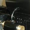
 1022 forum posts 127 photos | Mine are held with Loctite and a grub screw that has a small indent drilled in the axle, picture could have been clearer but I'm sure you'll get the drift. It does have 3 motors one for each axle. I did think of using a small tapered pin but so far this has been fine.
Edited By Bob Brown 1 on 15/04/2017 11:57:10 |
| Perko7 | 15/04/2017 13:50:02 |
| 452 forum posts 35 photos | Hi Bob, that looks ok for smaller gauges (garden railway sizes) but not secure enough for 5" gauge where the coupling rods are doing all the work of transmitting power to the axles. My cranks also include counterweights and are therefore quite a bit larger. Brian G, I was assuming drilling into the end of the axle (part in the axle and part in the crank like a key and as described elsewhere) but drilling across at 90 degrees would also work. I'd need to tip the loco on it's side to drill from underneath the crank as access from the top and sides is restricted by running boards and other fittings. I could just make the pin a light drive fit so it is easier to punch them out without heat if ever i needed to, The loctite would not be used for the pins, only for the cranks. The pins would only really be for locating the cranks in their correct positions. Once the loctite had set it would be doing most of the work. I'm slowly getting a better understanding of how to do it so will post an update after the first attempt. Got to make the crankpins first and then drill and ream all the holes in the cranks for the crankpins and for mounting on the axles. Cheers.
|
| duncan webster | 15/04/2017 15:53:16 |
| 5307 forum posts 83 photos | Make the holes first, it's a lot easier to make pins fit holes than vice versa, and a lot less material to chuck if you do get it wrong. Loctite on its own is plenty strong enough, the only sensible reason I can think of for pins is so that if you ever do remove the cranks it's easier to set them up next time. Rollpins are a good alternative to trying to make pins a light drive fit. Drilling the holes with the axles in situ is asking for trouble, can'y you take the axles out and do them under a drill press? |


Please login to post a reply.
Magazine Locator
Want the latest issue of Model Engineer or Model Engineers' Workshop? Use our magazine locator links to find your nearest stockist!
Sign up to our Newsletter
Sign up to our newsletter and get a free digital issue.
You can unsubscribe at anytime. View our privacy policy at www.mortons.co.uk/privacy
Latest Forum Posts
- *Oct 2023: FORUM MIGRATION TIMELINE*
05/10/2023 07:57:11 - Making ER11 collet chuck
05/10/2023 07:56:24 - What did you do today? 2023
05/10/2023 07:25:01 - Orrery
05/10/2023 06:00:41 - Wera hand-tools
05/10/2023 05:47:07 - New member
05/10/2023 04:40:11 - Problems with external pot on at1 vfd
05/10/2023 00:06:32 - Drain plug
04/10/2023 23:36:17 - digi phase converter for 10 machines.....
04/10/2023 23:13:48 - Winter Storage Of Locomotives
04/10/2023 21:02:11 - More Latest Posts...
- View All Topics
Support Our Partners


Shopping Partners
Subscription Offer

Latest "For Sale" Ads
- Reeves** - Rebuilt Royal Scot by Martin Evans
by John Broughton
£300.00 - BRITANNIA 5" GAUGE James Perrier
by Jon Seabright 1
£2,500.00 - Drill Grinder - for restoration
by Nigel Graham 2
£0.00 - WARCO WM18 MILLING MACHINE
by Alex Chudley
£1,200.00 - MYFORD SUPER 7 LATHE
by Alex Chudley
£2,000.00 - More "For Sale" Ads...
Latest "Wanted" Ads
- D1-3 backplate
by Michael Horley
Price Not Specified - fixed steady for a Colchester bantam mark1 800
by George Jervis
Price Not Specified - lbsc pansy
by JACK SIDEBOTHAM
Price Not Specified - Pratt Burnerd multifit chuck key.
by Tim Riome
Price Not Specified - BANDSAW BLADE WELDER
by HUGH
Price Not Specified - More "Wanted" Ads...
Get In Touch!
Do you want to contact the Model Engineer and Model Engineers' Workshop team?
You can contact us by phone, mail or email about the magazines including becoming a contributor, submitting reader's letters or making queries about articles. You can also get in touch about this website, advertising or other general issues.
Click THIS LINK for full contact details.
For subscription issues please see THIS LINK.
Digital Back Issues


Donate

 Register
 Log-in
Model Engineer Magazine
- Percival Marshall
- M.E. History
- LittleLEC
- M.E. Clock

ME Workshop
- An Adcock
- & Shipley
- Horizontal
- Mill

Subscribe Now
- Great savings
- Delivered to your door

Pre-order your copy!
- Delivered to your doorstep!
- Free UK delivery!
All Forum Topics > General Questions > 08 shunter quartering