Forum sponsored by:

WARCO WM-250 lathe family and WM16 mill - 001
........advice and support for owners.
| Rik Shaw | 15/05/2013 13:06:34 |
 1494 forum posts 403 photos | Several of us on here have agreed that owners of the above machines might find it useful to have a dedicated thread in order to exchange ideas and info. So, providing the moderators approve I'd like this to be the start. George, I am bench mounting my mill when it comes, would you be able to help by supplying the dimension from the bottom of the base casting to the underneath of the table. Thanks in advance. Rik |
| Thor 🇳🇴 | 15/05/2013 17:56:21 |
 1766 forum posts 46 photos | Hi Rik, my milling machine is not a Warco WM16, the head is slightly different with a MT 3 spindle taper. The rest is very similar (identical?) except for the colours. You can find a picture of it in my albums. On my milling machine the distance from bottom of base to underside of table is 105mm.
Regards Thor Edited By Thor on 15/05/2013 17:57:10 |
| Mark P. | 15/05/2013 20:18:23 |
 634 forum posts 9 photos | Hi chaps I'm with you I've got a WM-250 lathe and a WM16 mill. They both do most of what is asked of them, but I would like to hear of any mods and improvements others have made to theirs, eg bracing up the column of the WM16, I can find plenty of mods to X1's. Cheers Mark P. |
| Clive B | 15/05/2013 21:11:10 |
| 46 forum posts 21 photos | Rik, On my machine (Warco WM-16, circa 2006) the measurement from the underside of the base casting to the underside of the table itself is 90mm. However, do you mean to the underside of the handwheel (45mm), or the flange at the end of the table (73mm)? Just interested in what you need the measurement for. I have the WM-250 also, and would be very interested to hear what others have done to their machines. Clive |
| dcosta | 15/05/2013 22:08:13 |
| 496 forum posts 207 photos |
Hello Mark P. |
| Mark P. | 16/05/2013 10:48:52 |
634 forum posts 9 photos | Hello Dias, the BF20 looks very much like the WM16.Whilst I have had no real problems or complaints with it,I do tend to drive it quite hard and feel that bracing the column would help with the general stiffness of the machine.i think that because of the height of the column and the fact it is secured to the base at the bottom by 4 closely spaced bolts the overall ridgity is compromised, so bracing would help.I think that a 12mm thick steel gusset on either side of the column extending up maybe 150-200mm upwards and bolted to the base would help. Ideally I would like something like a Bridgeport but I do not have the access to get one into my workshop,it would have to come up a narrow alley up some steps and through 6 gates 2 of which are quite narrow. I welcome your thoughts and comments. Regards Mark P. |
| Rik Shaw | 16/05/2013 11:00:53 |
1494 forum posts 403 photos | Clive - Thanks very much for those dimensions. The reason I need them is to get the castored cupboard the mill will sit on to the correct height. The cupboard in its storage position is hard up against a fixed lathe bench and the RH side of the mill table will need to pass over this bench. Its all about available space (or lack of it)! Thanks again. ------ Rik |
| mechman48 | 16/05/2013 14:41:49 |
 2947 forum posts 468 photos | Hi all Mark P; - I have never found the need to consider bracing the column, I have put on a d.o.c. of 1mm (CI, MS, Ally' & Brass) without it complaining, from your post it seems that you are putting quite hefty cuts on it, I would be wary of stripping the intermediate plastic gear if too much is put on, unless you've already remedied that? Rik,- as with Thors machine the height from my stand top to the underside of the table is 106mm (wouldn't guarantee that all casting batches measure the same), that is to the bottom of the dovetail slides. Thor - from your album it looks like yours is the Amadeal version of the WM18 if it has the MT3 (no connection) as do the WM 18, BF20L, PC45, Grizzly G0704 & Optimum BF20, the only differences I can note is the layout of the electrics, switching & colour scheme, looking at the WM16 & Grizzly G0704 parts lists, they are identical, If anyone wants a comprehensive manual & parts list look up .. grizzlyG0704.com. .. the manual for my WM16 looks as though its pages are a Chinglish version extracted from Grizzly's manual. As far as mods to my machines goes,- so far I have fitted DRO's to the X & Y axes on the mill ,altered the chip/splash guard & fitted a couple of stops to the head to maintain 'zero tramming', any angle work needed (very little so far) I have used my angle vice. On my 250 V-F.. - I have modified the topslide to take a Dickson type toolpost '00' size, (simply as I had it plus 10 holders from previous), although I'm sure it will take the '0' version plus Warcos version (item 9009.250), from their blurb it seems that you have to ask them to machine these to fit the 250V-F (extra cost ?) I actually machined the boss off my topslide to accomodate the QCTP, if I need to use the original t/post then it would be to simply machine up a boss/collar to fit over the QCTP stud. I have modified the compound slide friction collar by adding a machined knurled collar for easier grip as the original set up was small difficult to get my (fat) thumb & finger in to grip..much improved. The chuck guard has been modified to allow me to see better, the original configuration had the frame edge blocking my view down onto the chuck (nitpicking) I have a couple of ' to do it' items to get on with.. 1. Replace the compound gib strip to brass, proper size, as the orig' is just an ms strip fitted & leaves a lot to be desired 2. Make up a saddle lock for more solid saddle locking when facing / parting off, the original is a allen screw locking system on the bottom right corner(I'm sure all of you are well aware of this). 3. Fit a coolant system to lathe / mill. I have a temp system I use for both at the mo' All mods can be be seen in my album pics; if anyone has already done similar 'to do it' mods would appreciate pics /drawings. Am in the process of updating my album so if you can't see any pics mentioned let me know. Cheers for now George
Edited By mechman48 on 16/05/2013 14:50:03 |
| mechman48 | 16/05/2013 14:45:23 |
2947 forum posts 468 photos | ps Mea culpa, the correct Grizzly link is |
| Mark P. | 16/05/2013 17:13:12 |
634 forum posts 9 photos | Hi George, although I I do put on quite heavy cuts I haven't had any problems with the intermediate gears(yet!) I believe that a set of replacement steel gears are available but haven't been able to track any down. I am also considering replacing the original motor with a 3 phase motor and a VFD this will hopefully happen in the not to distant future. Regards Mark P. |
| Rik Shaw | 16/05/2013 19:09:23 |
1494 forum posts 403 photos | Mark - I am fairly certain that I read somewhere very recently that Arc Euro do replacement steel gears. I also seem to remember reading that the plastic gear was there to minimise damage to the rest of the machine in the event of a stack-up. Thanks to George for the Grizzly link. I printed the PDF earlier and was amazed to find that my second hand HP LaserJet was able to use a duplex mode and print double sided - never knew it could do that until now - whoopee! Rik |
| Gone Away | 16/05/2013 22:56:16 |
| 829 forum posts 1 photos |
Posted by Mark P. on 16/05/2013 17:13:12:
I believe that a set of replacement steel gears are available but haven't been able to track any down. Raises the question .... has anyone seen any instructions/write-up/blog etc concerning exactly how you get to the gears in these mills to replace them. I took a quick look while I was working on the head for another reason and it didn't seem at all obvious (to me). |
| Springbok | 17/05/2013 07:49:03 |
 879 forum posts 34 photos | Hi try grizzly.com for decent manuals (they write there own) that can be downloaded, Yanks are a bit ott on h&s they call by different names but the same kit, just look for a pic of your one I have the larger WMT and a Chester 626 mill and managed to print of very decent manuals
Like this thread and will be following it. |
| dcosta | 17/05/2013 10:03:01 |
| 496 forum posts 207 photos |
Hello Sid, Good morning! Edited By dcosta on 17/05/2013 10:03:34 |
| Rik Shaw | 17/05/2013 19:10:53 |
1494 forum posts 403 photos | Most of my time in engineering was on either lathes but more particularly on jig boring and grinding /universal/jig/profile/cutter/surface etc. I never did get involved with milling machines however. So, a bit of advice please re: using the WM16 mill with its 2MT spindle taper. I appreciate the need to secure the tool holding arbour with a threaded drawbar on other milling machines so: A ::: Is the WM16 drawbar just an ejection device or is it also a retaining device? B ::: All of my 2MT taper sleeves/drills have a tang and not a threaded hole, will they fit in the WM16 spindle? C ::: If the drawbar IS threaded on a metric WM16 what size is the thread? Finally, I'd like to use an E25 (I already have a set of collets) collet chuck with a 2MT taper to hold cutters. Am I going about this the right way? Rik -----------PS........Thanks for the links Dias
|
| Mark P. | 17/05/2013 19:39:37 |
634 forum posts 9 photos | Hi Rik, tanged MT2 drill bits will fit but you may have to grind a bit of the side of the tang. The drawbar is an ejection and retaining device,the thread on the supplied drawbars are M10x1.5 and 3/8" whitworth. You should be able to use your MT2 collet chuck in a WM16 provided it has a tapped hole for a drawbar,I would advise against using non drawbar accessories as vibration ma cause the accessories to become loose with disastrous consequences to job and accessory. Regards Mark P. |
| Thor 🇳🇴 | 17/05/2013 19:58:12 |
1766 forum posts 46 photos | Hi George, my milling machine is not as heavy as the Warco WM 18. I guess it is similar (identical ?) to the Weiss WMD25. My milling machine weighs about 120 kg. I like the DRO you installed on your milling machine. Mechman, the g0704.com website has a lot of good advice for the WM 16 and similar milling machines. Thor |
| Ed Duffner | 17/05/2013 20:31:21 |
| 863 forum posts 104 photos | Hi Rik, A: The drawbar is just a retaining device, not an ejection device as such. The manual says to undo the securing nut slightly and strike the top of the drawbar with a rubber mallet to free the tapered tool. I believe some of the guys here on the forum have made some kind of bush which will make the bar self ejecting. B: I imagine this would be similar to a pillar drill. I wouldn't like to say yes or no to this as I'm not experinced enough to confirm use of tanged drills in the WM-16 quill. I don't think there's a slot to insert a drift so it'll be a bu**er trying to get those drills out. Maybe a 2MT/2MT extension sleeve with a drift slot would do it. C: The drawbar is threaded M10 and when new you also get a 3/8" drawbar for imperial tooling. D: I use an ER25 collet chuck with the M10 drawbar and a set of ER collets.
BTW, I replied to your other thread asking about Waro WM-16 base dimensions.
Cheers,
|
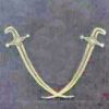
| Stub Mandrel | 17/05/2013 21:02:11 |
 4318 forum posts 291 photos 1 articles | This is my self-ejecting drawbar for an X2 mill. I don't know about the VM16, but the X2 has a left hand thread on the spindle. The drawbar has an 8mm square on the end for a spanner. Neil
|
| dcosta | 17/05/2013 21:37:29 |
| 496 forum posts 207 photos |
Hello Rick.
|


Please login to post a reply.
Magazine Locator
Want the latest issue of Model Engineer or Model Engineers' Workshop? Use our magazine locator links to find your nearest stockist!
Sign up to our Newsletter
Sign up to our newsletter and get a free digital issue.
You can unsubscribe at anytime. View our privacy policy at www.mortons.co.uk/privacy
Latest Forum Posts
- *Oct 2023: FORUM MIGRATION TIMELINE*
05/10/2023 07:57:11 - Making ER11 collet chuck
05/10/2023 07:56:24 - What did you do today? 2023
05/10/2023 07:25:01 - Orrery
05/10/2023 06:00:41 - Wera hand-tools
05/10/2023 05:47:07 - New member
05/10/2023 04:40:11 - Problems with external pot on at1 vfd
05/10/2023 00:06:32 - Drain plug
04/10/2023 23:36:17 - digi phase converter for 10 machines.....
04/10/2023 23:13:48 - Winter Storage Of Locomotives
04/10/2023 21:02:11 - More Latest Posts...
- View All Topics
Support Our Partners


Shopping Partners
Subscription Offer

Latest "For Sale" Ads
- Reeves** - Rebuilt Royal Scot by Martin Evans
by John Broughton
£300.00 - BRITANNIA 5" GAUGE James Perrier
by Jon Seabright 1
£2,500.00 - Drill Grinder - for restoration
by Nigel Graham 2
£0.00 - WARCO WM18 MILLING MACHINE
by Alex Chudley
£1,200.00 - MYFORD SUPER 7 LATHE
by Alex Chudley
£2,000.00 - More "For Sale" Ads...
Latest "Wanted" Ads
- D1-3 backplate
by Michael Horley
Price Not Specified - fixed steady for a Colchester bantam mark1 800
by George Jervis
Price Not Specified - lbsc pansy
by JACK SIDEBOTHAM
Price Not Specified - Pratt Burnerd multifit chuck key.
by Tim Riome
Price Not Specified - BANDSAW BLADE WELDER
by HUGH
Price Not Specified - More "Wanted" Ads...
Get In Touch!
Do you want to contact the Model Engineer and Model Engineers' Workshop team?
You can contact us by phone, mail or email about the magazines including becoming a contributor, submitting reader's letters or making queries about articles. You can also get in touch about this website, advertising or other general issues.
Click THIS LINK for full contact details.
For subscription issues please see THIS LINK.
Digital Back Issues


Donate

 Register
 Log-in
Model Engineer Magazine
- Percival Marshall
- M.E. History
- LittleLEC
- M.E. Clock

ME Workshop
- An Adcock
- & Shipley
- Horizontal
- Mill

Subscribe Now
- Great savings
- Delivered to your door

Pre-order your copy!
- Delivered to your doorstep!
- Free UK delivery!
All Forum Topics > Workshop Tools and Tooling > WARCO WM-250 lathe family and WM16 mill - 001