Forum sponsored by:

Suggestions please Vol3
| Ian P | 30/01/2012 20:20:12 |
 2747 forum posts 123 photos | Graham
Unless I have completely misunderstood your requirement what you are requesting/suggesting would be almost as complicated/expensive as a DRO with scales but have none of the advantages.
It would be fairly simple to fit a rotary encoder connected to a digital up/down counter to the leadscrews but it would need an encoder disk with at least twice as many increments as the standard dial just to get the same resolution. By the time backlash has been taken into account what you would end up with would not be very accurate.
I doubt you have zero electronic skills! but none would be needed anyway to fit a ready made DRO system. There are some simple ones these days and if you are happy with totally separate displays for each axis why not consider fitting the 'igaging' scales (Arc Euro have them). From the description they would need some extra encasing to stop swarf getting in, but for their accuracy they are very cheap, its similar to the very common Chinese calipers so not what you would call traceable standards but they are reasonably repeatable so fine for ME use rather than commercial production.
Ian P
|
| John Stevenson | 30/01/2012 21:27:24 |
 5068 forum posts 3 photos | Graham, Can't place what you are talking about but I understand the principle. Arc carries these digital 'dials'  But they need to operate on a 20 tpi screw or be geared to represent a 20 tpi screw for the encoder to count correctly. At 20 tpi they are direct reading or with 10 tpi they give half / radius reading. HTH. John S. PS. BTW they fit straight onto a Taig mill as they are on 1/2" x 20 UNF screws. |
| Cornish Jack | 30/01/2012 21:31:26 |
| 1228 forum posts 172 photos | Graham, coincidentally I saw, yesterday, on You Tube something which might be suitable. It was a video of a dividing head in use but with a rod extension on the rotating handle positioned such that it struck a mechanical counter actuator lever once on each revolution. Looked to be ultra-simple in concept and operation. Problem? ... can't remember the location. Will have a search if it sounds as if it might be useful. Rgds Bill PS Found it!! www.youtube.com/watch?v=Y2QBZQM0d_8 B Edited By Cornish Jack on 30/01/2012 21:35:33 |
| Les Jones 1 | 30/01/2012 21:47:38 |
| 2292 forum posts 159 photos | Hi Gray, The first digital readout I used on the X axis of my mill used the method you describe. If you do not already have the rotary encoders the 'igaging' scales that Ian P mentioned are probably a cheaper solution and gets round the backlash problem. If you do already have the rotary encoders I will see if I can find the information on the unit I designed for my mill. Les. |
| blowlamp | 31/01/2012 11:40:48 |
 1885 forum posts 111 photos | You could try here:
I believe they are intended for angular measurement and they plug directly into their display units, so it might (just) be possible to configure them to display as linear movement.
I have the digital dials that John S mentions fitted to my Clarke CL300 lathe and they work OK, but they each get through a battery about every 2-3 months.
If all you really need is whole mm's, then why not get some crisply graduated rules (rulers
 ) and fit them to each axis and make some adjustable reference pointers to help you keep track of position? ) and fit them to each axis and make some adjustable reference pointers to help you keep track of position?Would a conventional DRO work for you, if it were possible to disable some of the digits after the decimal place, because I think that might be possible with some units?
Maybe have a word with the people at the above link if that's an option.
Martin. Edited By blowlamp on 31/01/2012 11:45:06 |
| Les Jones 1 | 31/01/2012 13:08:45 |
| 2292 forum posts 159 photos | Hi Gray, For your Emco you would only need an encoder with three (Or a multiple of three.) pulses per revolution. One possibility is the encoders used in mechanical computer mouse. (One that has a ball.) These are very small so they would be easier to fit in the space available. Most mice have optical encoders but one I have just looked at is just contacts on a disk with the encoder pattern as a PCB. I think this type encoder can be bought. They look just like a potentiometer but can rotate continuously. An example of these is This item on Ebay. I should be able to design a display unit to work with these encoders. Would you prefer an LCD or LED display ? For the unit to display metric or imperial the encoder would need to give more pulses per rev so the truncation of the result of division calculations did not give a significant error. The normal method to switch between units is to multiply by 125 and divide by 256 for inches and multiply by 127 and divide by 1024 for metric. having the divide part of the calculation as a power of 2 makes the division very easy in binary. (Other similar divisors could be used.) For the Emco a variation of Cornish Jack's suggestion but using a tape position counter from an old cassette or open reel tape recorder might work as these counters normally have a zero button. All that would be needed would be gearing up 3:1 from the leadscrew. Les. |
| Les Jones 1 | 31/01/2012 15:11:39 |
| 2292 forum posts 159 photos | Hi Gray, I have never used these switch contact type of encoders. They have the potential to generate noisy signals which may require filtering either electrically or in software in the microcontroller. When they are used in a mouse it does not matter if they miss a step but in your application a missed step is 1/8 of turn of the leadscrew. (The ones in the link on Ebay gave 24 pulses per rev.) The two outputs on these encoders allow the counter to count up or down. The reason for asking about preference of display type is because the microcontroller cannot afford to miss seeing the signals from the encoder while it is doing something else like multiplexing an LED display. This means that the software has to be designed from the start knowing the type of display being used. The valve type displays you mention are called "Nixie" tubes. They would be more complex to drive from a microcontroller as they work on fairly high voltage. This is the schematic for the display I built for my mill many years ago. This uses an LCD display. 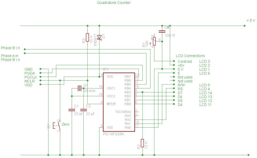 Les. |
| blowlamp | 31/01/2012 15:50:00 |
1885 forum posts 111 photos | Graham.
If it is just an excess of numbers on the display that's the problem, then I can't help thinking that a conventional 2 axis DRO system with a couple of blobs of BluTack/tape over the offending digits might serve you best in the long run.
As a minimum with the modern DRO's, you get PCD bolt hole and points along a line (at any angle) functions, which should save you some time compared to setting up a rotary table or working out the coordinates for yourself.
You probably wouldn't be able to fix it yourself, should the need ever arise, but I think they're quite reliable anyway. Good luck with however you do it.
Martin.
|
| mgnbuk | 31/01/2012 20:03:42 |
| 1394 forum posts 103 photos | Would something like this Ebay 250981106884 do what you want ? Geared up 1:3 from the leadscrew to read out whole millimetres. The listing doesn't say whether or not it counts both ways - might be worth asking the seller, but cheap enough to experiment with. Regards, Nigel B. |
| Terryd | 01/02/2012 05:47:06 |
 1946 forum posts 179 photos | Hello Graham, There is a design for a
tachometer using simple, cheap components and an inexpensive Chinese 4
digit LED display in issue MEW 147. Although it is a tachometer, I intend to build for
exactly the same purpose as yourself. The original article uses an
optical sensor (from an old mouse or drive etc) to read a slotted disc. This just needs one slot for recording one rotation of a handwheel or a Hall effect method could be substituted. Here is the
circuit as it appears in MEW 147 in the archive if you have access. If
not I have a copy I could scan and send for your perusal. The power
supply could be based on an old phone etc charger or even a modified computer
PSU. A typical 4 digit frequency meter/counter display with 14mm digits
is here on eBay at £8.70 with free delivery.but there are others at varying prices as is normal. Click on the picture for a larger view. 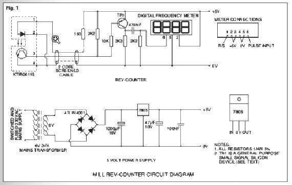 Best regards Terry Edited By Terryd on 01/02/2012 06:06:42 |
| Les Jones 1 | 01/02/2012 10:05:16 |
| 2292 forum posts 159 photos | Terry, My understanding is that Gray requires a counter that will decrement when the direction of rotation is reversed so it will keep track of the position of the slide. The counter you describe would always increment. Gray, I've found one of the mechanical counters I suggested. I think it came out of a VHS video recorder. This one has two problems. 1 The units increment about every 1.5 revs of the input shaft. This could be solved by adjusting the gearing. 2 The units increment smoothly rather than jumping from one digit to the next. You could possibly manage with this as the graduations on the dial would let you know if it was just below or just after the units digit on the counter. Les. |
| Michael Gilligan | 01/02/2012 12:03:59 |
 23121 forum posts 1360 photos | Gray, If you do go the electronic route ... you need a "quadrature decoder" to detect direction. A few years back, there was a lot of interest in using the shaft encoders from a computer mouse ... this would seem ideal. There should be lots of guidance around on the web. MichaelG. |
| wotsit | 01/02/2012 14:58:55 |
| 188 forum posts 1 photos | My wife uses a mechanical counter on her knitting machine to keep track of the number of times the carriage has been traversed. I can remember seeing these years ago used for many purposes, there were handheld ones for lapcounting when running, or for such things as stitch counting when knitting. The one one the machine has a simple ratchet which allows it to increment in only one direction, and from the look if it, it could be easily disable to allow increment/decrement operation. - would this kind of thing do the job? |
| Les Jones 1 | 01/02/2012 15:19:22 |
| 2292 forum posts 159 photos | Hi Gray, The mechanical counter from the video recorder does not have any part number on it. I think it was made for this recorder. I have tried one of the switch type quadrature encoders from the old computer mouse with the counter that I used with the quadrature encoder on my mill many years ago. To get it to work reliably I had to first clean the contacts and then filter the inputs to the counter with 100 nf capacitors. I found this encoder gave 36 pulses per rev. Les. Edited By Les Jones 1 on 01/02/2012 15:20:04 |
| Michael Gilligan | 01/02/2012 16:33:34 |
23121 forum posts 1360 photos | Les, That must have been an ancient mouse ... what model was it? Every mouse I have stripped-down had optical shaft encoders: of course, the latest ones use video camera technology, but we're getting a bit out of my depth there. MichaelG. |
| Les Jones 1 | 01/02/2012 17:44:53 |
| 2292 forum posts 159 photos | Hi Michael, This is the only mouse I have seen using this type of encoder. It is probably one of the original serial mice which came before the PS2 mice. (I have cut the cable off so I can't be sure.) Hi Gray, I think these modern optical mice work by recognising patterns on the surface of the mouse mat and working out how far it has moved in its field of view as the mouse is moved. These mice would be no good for your purpose. Let me know if you would like either the tape counter or the encoders from the mouse. Although the counter could probably be made to work I think it would be better to use an item that could be obtained again. Farnell have a range of these switch type encoders but I think an optical unit would be better. As you only need three quadrature cycles per rev it should be possible to make one yourself. It could probably even be made using reflective type sensors such as the SY-CR102 from Maplin. I also have a program that will print out the pattern to make encoder disks. Let me know if you would like a copy of that. One way to try to make a simple sensor would be to use some hex bar and paint three faces black and three faces white and use this with the reflective sensors.The sensors would need to be spaced 30 degrees apart. (Or 90, 150, 210 etc) One other thing you need to consider is when the original scale on the leadscrew is at its zero position you will not be quite sure if the digital display hasjust incremented or is just about to increment. Having the least significant digit displaying zero or 0.5 would solve that problem. Les |
| Bazyle | 01/02/2012 18:18:07 |
 6956 forum posts 229 photos | I seem to be missing something obvious. Why does it need to count down if you only want it to count in one direction? Do you want 99, 98, 97 or -1 -2 -3? Isn't a mechanical downcounter just an upcounter with the numbers painted on in reverse order? |
| Michael Gilligan | 01/02/2012 19:31:15 |
23121 forum posts 1360 photos | Thanks Les ... must try to find one or those! It's off-topic really, but: here's a useful link for anyone interested in the workings of the Optical Mice. http://tim.cexx.org/?p=613 MichaelG. |
| Les Jones 1 | 01/02/2012 20:11:00 |
| 2292 forum posts 159 photos | Hi Gray, It will be possible to modify the code so that negative values are displayed as zero. The code in the unit at the moment is not the original that displayed position in mm when it was on the mill. It has been modified for testing other units that display the output from the Chinese calipers / scales. It displays the count in decimal on the top line of the display together with a minus sign for negative numbers, On the bottom line it displays the value as a 24 bit hexadecimal number. If the top bit of this number is set then the decimal display is considered to be negative. Les. Edited By Les Jones 1 on 01/02/2012 20:13:15 |
| Ian S C | 02/02/2012 00:35:19 |
 7468 forum posts 230 photos | I know nothing! Would it be possible to use an optical mouse as a tachometer by somehow reprogramming its responce, ie to put up a figure (rpm) instead of the moving cursor. As I said "I know nothing" about how these things work. Ian S C |
Please login to post a reply.
Magazine Locator
Want the latest issue of Model Engineer or Model Engineers' Workshop? Use our magazine locator links to find your nearest stockist!
Sign up to our Newsletter
Sign up to our newsletter and get a free digital issue.
You can unsubscribe at anytime. View our privacy policy at www.mortons.co.uk/privacy
Latest Forum Posts
- *Oct 2023: FORUM MIGRATION TIMELINE*
05/10/2023 07:57:11 - Making ER11 collet chuck
05/10/2023 07:56:24 - What did you do today? 2023
05/10/2023 07:25:01 - Orrery
05/10/2023 06:00:41 - Wera hand-tools
05/10/2023 05:47:07 - New member
05/10/2023 04:40:11 - Problems with external pot on at1 vfd
05/10/2023 00:06:32 - Drain plug
04/10/2023 23:36:17 - digi phase converter for 10 machines.....
04/10/2023 23:13:48 - Winter Storage Of Locomotives
04/10/2023 21:02:11 - More Latest Posts...
- View All Topics
Support Our Partners


Shopping Partners
Subscription Offer

Latest "For Sale" Ads
- Reeves** - Rebuilt Royal Scot by Martin Evans
by John Broughton
£300.00 - BRITANNIA 5" GAUGE James Perrier
by Jon Seabright 1
£2,500.00 - Drill Grinder - for restoration
by Nigel Graham 2
£0.00 - WARCO WM18 MILLING MACHINE
by Alex Chudley
£1,200.00 - MYFORD SUPER 7 LATHE
by Alex Chudley
£2,000.00 - More "For Sale" Ads...
Latest "Wanted" Ads
- D1-3 backplate
by Michael Horley
Price Not Specified - fixed steady for a Colchester bantam mark1 800
by George Jervis
Price Not Specified - lbsc pansy
by JACK SIDEBOTHAM
Price Not Specified - Pratt Burnerd multifit chuck key.
by Tim Riome
Price Not Specified - BANDSAW BLADE WELDER
by HUGH
Price Not Specified - More "Wanted" Ads...
Get In Touch!
Do you want to contact the Model Engineer and Model Engineers' Workshop team?
You can contact us by phone, mail or email about the magazines including becoming a contributor, submitting reader's letters or making queries about articles. You can also get in touch about this website, advertising or other general issues.
Click THIS LINK for full contact details.
For subscription issues please see THIS LINK.
Digital Back Issues


Donate

 Register
 Log-in
Model Engineer Magazine
- Percival Marshall
- M.E. History
- LittleLEC
- M.E. Clock

ME Workshop
- An Adcock
- & Shipley
- Horizontal
- Mill

Subscribe Now
- Great savings
- Delivered to your door

Pre-order your copy!
- Delivered to your doorstep!
- Free UK delivery!
All Forum Topics > General Questions > Suggestions please Vol3