Forum sponsored by:

A plastic valve
De-burring an internal edge
| Sam Stones | 07/06/2011 07:58:51 |
 922 forum posts 332 photos |
Some considerable time ago, and quite by chance, I found myself designing and making a miniature five-ported hydraulic valve for use in medical research. It was machined from solid Perspex (PMM) and measured about 26mm long by 22mm wide by 16mm deep. It was to be secured to a microscope stage operating at fairly high magnification, and hence had to be remotely controlled to avoid generating vibration. I chose to make the spool from Teflon (PTFE), which had to seal completely, two fluids being switched by the valve as the fluids passed through it. In other words, there must be no leakage. The main bore of about 9mm diameter had to be machined and reamed with the minimal amount of frictional heat, so that final lapping (essential for accuracy and finish), didn’t cause crazing. Some liquids can be seen to induce stress-cracking from inbuilt stress, (a bit like happens when a high density polyethylene injection moulding comes into contact with detergent solutions). This crazing of the PMM was initially found to be a significant setback, until I developed a satisfactory low heat machining solution. However, the real problem came when drilling the five 1.0mm port holes. As these broke through into the 9mm bore, you would expect a significant burr to be formed on the inside.
There was. Five of them.
The action of shunting the PTFE spool over this rough surface would immediately damage the spool and defeat the purpose of the valve.
Once the word got out, I finished up making and selling several dozen of these individually manufactured valves to various research groups around the world. My question is :- How would you deal with the burrs?
I'll post my method in a few days.
Sam |
| Weldsol | 07/06/2011 08:41:28 |
| 74 forum posts | You could put a sacraficial bar in the hole and drill into that, so that no burr is raised
|
| PekkaNF | 07/06/2011 09:12:54 |
| 96 forum posts 12 photos | Heat is used to "smooth" edges of many plastics on many processes. This is ofcource counter productive here. Maybe you first drilled the ports, then reamed spool hole, then insertted a flushing spool and purged the lines with suitable (particle loaded???) medium. Just maybe a drap of solvent and/or detergent. Then apropriate cleaning? I'm not big on machining PTFE. I like POM, machines really nice. But sometimes you have to chose materials for medium. Did the PTFE ever creep or deform? You probably needed something to push or pull the spool Pekka |
| methusala | 07/06/2011 09:42:18 |
| 32 forum posts | Hi Sam, In L. Sparey's book, "The amateur's lathe" he states {The picture (B) shows a drill specially ground for ebonite , bakelite and other plastics. the steep angle of the point will be noted,also the large amount of clearance.} Many years ago a tool maker was given the job of drilling a number of 1/8 holes in some polypropolyne components, he used a drill sharpened with a normal drill (59') and the burrs were horrendous. A few weeks later I got the same job to do, and remembering the advice from L. Sparey's book I sharpened the drill with an included angle of about 72' and to my reiief without any sign of a burr. He also states that you should drill it dry with a high drilling speed, I would be wary of the high drilling speed , as you don't want create too much heat and possibly melt the plastic. Hope this is of some use to you. colin. |
| Ian S C | 07/06/2011 11:59:22 |
 7468 forum posts 230 photos | colin, could you drill with the pespex either submerged in, or flooded with water to keep it cool? Ian S C |
| methusala | 07/06/2011 13:08:48 |
| 32 forum posts | Hi Ian, I haven't given that aspect of the job too much thought. The job I did all those years ago was drilled dry with the drilling m/c set to the mid range speed, and clearing the flutes frequently. If you need to keep things cool with water it would be better to submerge it rather than flood it , as that would make it a very messy process . Colin. |
| Sam Stones | 09/06/2011 00:55:10 |
922 forum posts 332 photos |
I intend to hold off a little longer before explaining my de-burring method wrt drilling 1.0mm holes through PMM. Hints at my method have already appeared.
Instead, I shall put some comments forward in response to the above replies.
To obtain a positive seal between the inside of the PMM and the PTFE spool, while bearing in mind that PTFE does creep, I made the centre section of the PTFE spools a small amount larger in diameter, ie. about 0.008mm (0.0003"). This was all I was prepared to trust from my lathe in a semi-production sense. The unfilled PTFE was ideal in terms of its low friction characteristics, especially that of `stick’ friction. Both materials (PTFE and PMM) had to be relatively inert to the fluids being processed. In response to PekkaNF’s comments about machining PTFE, it's a material which is not easy to grip. Unlike POM (polyacetal, Delrin,) which is more rigid, and swarf normally comes away cleanly (unless static builds up and pulls the swarf onto the workpiece), unfilled PTFE is soft and slippery. Its creep resistance is very low too, so it becomes necessary to surround the workpiece with metal as a means of reducing movement (creep). At the time, I had quick release collets, so gripping the PTFE bar-stock was not an issue. Another aspect which came to my notice in terms of the performance of the valve, was that at 19 degrees C, PTFE goes through a phase change and sharply increases in volume. This had to be taken into consideration for valves specified for use in applications where the operating temperatures were above 0 degs C, but below 19 degs C. For these special lower temperature versions, I made the diameter of the PTFE spools a small amount larger to accommodate this drop in volume. I also had to supply special instructions for when the valve was not in use. Researchers could either keep the valves in the fridge or strip them down to remove the spool. Storing the separate parts at room temperature was not a problem, although an important part of preparation for use was to reduce their temperature to below 19 degrees, and to keep them below 19C while in use. Returning to de-burring, I think Weldsol’s comments about using a sacrificial bar has merit, although I needed to make quite a few of these valves, so it would be necessary to jig the bar to accurately locate the hole centres and avoid significant (bar) wastage. This wouldn’t have been too much of an issue since I was already drilling the holes with a drilling jig. However, I do wonder about what would happen if the drill wandered slightly. Colin - I’ve just returned Sparey’s book to the library, (after reading about his method for winding helical springs). However, his comments about `... drilling Ebonite, Bakelite and other plastics ...’ reminded me that drill-pointing to a very steep angle was the method being used in the plastics factory where I started my apprenticeship in 1950.
There were very few thermoplastics in those days, so melting was not a real issue. These days, we are inundated with a huge variety of mainly thermoplastics. As it happens, before I started my own business, I was a technical officer servicing polypropylene (PP). One of this material’s characteristics is its ability to be hinged. The so called "Living Hinge".
When machining PP (which begins to soften at about 130 degs C and melts quite sharply at about 175 degs C), this hinging property is also responsible for producing very ragged edges.
It doesn't want to let go!
 The best results with most thermoplastics appears to be having very sharp cutters like woodworking tools, lots of swarf clearance, and reducing the cutting speed.
Keeping the work wet will help to reduce the heat build up. I could go on about PP but that’s another story.
Regards to all,
 Sam
Edited By Sam Stones on 09/06/2011 01:02:22
I've just remembered. I arranged the spool to be pushed back and forth hydraulically. The source of this hydraulic `power' was via two 1 ml hyper-dermic syringes. Edited By Sam Stones on 09/06/2011 01:06:49 |
| PekkaNF | 09/06/2011 13:17:36 |
| 96 forum posts 12 photos | PTFE have it's uses, but it takes some understanding. Once I used it as a bearing AND brake. Had to turn OD to dimenssion, ID only to inser tool, primed PTFE cylinder and aluminium boss, added accelerator, glued them together (had to work fast thus jig and inser tool) and then turned ID to a dimenssion with one point internal tool..... Tried different methods, but PTFE creeps and does not respect mechanical fasteners  It's not too difficult to dril/turn just to get workholding right or the dimenssions are down to tubes. I liked your spool actuation! Sounds like stuff two molecularbiology scientists used to talk "we have to get this cooled dna to catalysista fast and then zap it with a lazer and then gather readings and hope they are not all over the walls" . They said that they wished they could have afforded me for the lab. And I tought I was badly paid, but they had to do they own tools and many componenest could have been agguired easier, but no-one come to think hiring somebody of a little industrial backgound. Remember many syringes actuated with a stepper motor to give a accurate rate of material flow. Many elastomer machining problems are fixed with right temperature. Often some cooling. Like freezing some rubber and then turning or drilling it. At -30C some plastics you can't regognice same. Or some high speed, on slow speed material seems viscous, but it "hardens" when you spin it fast and then pecdrill avoiding heating the tool tha leads to all the terible problems. Like a spider inside the table saw. Pekka |
| Pat | 09/06/2011 14:30:55 |
| 94 forum posts 1 photos |
One has to ask why perspex and why PTFE. Both materials have characteristics that are not ideal for making change over valves with next to no leakage as you have discovered.
I would have expected glass and ceramic to be the materials of choice. Both materials are easy to cut and grind using plenty of water and a diamond grit tool. A disk rather than a shuttle valve might simplify the design further and might still have the properties required by the researchers. A disc valve would be easy to make so that it could be dismantled for cleaning if that were an issue.
Also a disc valve would be easy to integrate with a glass microscope slide.
Regrads - Pat
Edited By Pat on 09/06/2011 14:43:37 Edited By Pat on 09/06/2011 14:45:01 |
| Versaboss | 09/06/2011 15:26:41 |
| 512 forum posts 77 photos | Amazing, Sam. You turn PTFE to dimensions measured in micrometers, so I suppose the tolerances are at least also in that region. I pull my hat, if only I had one ! May I ask what kind of lathe you use for that? Greetings, Hansrudolf
|
| Andrew Johnston | 09/06/2011 18:40:35 |
 7061 forum posts 719 photos | Plug the main bore before drilling. Drill through body and into plug. Remove plug; result no burrs. Regards, Andrew |
| Sam Stones | 10/06/2011 01:23:19 |
922 forum posts 332 photos |
Gentlemen, Thank you for your compliments, I’m only pleased to have somewhere to divulge some of my `tricks’. Before I disclose my method of de-burring the 1.0mm holes into the body of the PMM (Perspex) valves, I need to make a couple of comments about the more recent postings. I fully agree with Pekka regarding the machining and use of unfilled PTFE (Teflon). However, once its basic properties like creep, coefficient of friction, and inertness are understood, these can be dealt with as required. Pekka, your comments have aroused my curiosity. I suspect that you have worked in a research environment where these valves (or similar) were in use. I designed them specifically for one task in a biological research laboratory. From your other comments, I have to say that I also developed and made several other pieces of laboratory equipment, none the least being an infusion pump which would physically accept standard syringes from 5ml to 50 ml. Stepper motors were indeed used as the motive force, while the engagement and re-setting of the pump and syringe was achieved using a gearing-down lead-screw system not unlike a lathe split-nut arrangement. As I recall, with a wide range of speeds and syringes, discharge amounts could range from a millilitre or two over several hours, through to a relatively quick discharge of 50ml in just a few minutes. Another very serious semi-production task I developed, also involved machining elastomers. This was where the kitchen freezer became an import part of the equipment. It was of course, necessary to push the frozen food to one side, to make room for the items to be `frozen’. Around the mid 80's, both of my kids were heavily into roller skating, and the polyurethane wheels would wear unevenly. Over a number of weekends, a semi-production line began to evolve as more and more kids asked for their wheels to be machined.
I found that a wheel reduced in temperature to between minus 15C and minus 20C could be brought back into service to an acceptable `standard’ rather quickly. Setting the lathe feed to about 20tpi produced a grooved finish which the kids loved and presumably bragged about. The single point tool was given a very steep top rake similar to that which I would use for aluminium. A hidden benefit to this operation was that a slight amount of condensation developed on the wheels which seemed to improve the so-called cutting action. In hindsight, slicing rather than cutting would better describe this action.
Coping with the high `discharge’ rate of the polyurethane swarf was perhaps the hardest part of this production line, until my son and I decided to let the swarf wrap itself around the wheels and remove it later. A sharp Stanley knife worked wonders. As for the PTFE spools, and to pick up on the comments from Pat, Hansrudolf, and Andrew. Using the 1ml syringes as the `power’ source as mentioned before, the spool was caused to slide a mere 2mm, so that either one of two fluids could be switched rapidly as they were directed into the specimen bath. A material combination with minimal stick-friction was required. The best materials I had access to, and which were suitable for my modest home workshop were polymethyl methacrylate (PMM - better known as Perspex), and polytetrafluoroethylene (PTFE - better known as Teflon). Together, and with the degree of fit I had determined as suitable, these two materials produced virtually no stick friction, and provided a positive seal between the adjacent fluid channels. Since you asked Hansrudolf, all of my work in making these valves was carried out on my Myford ML7, and a nerve-wracking Chinese mill/drill. It wasn’t (and dare I suggest still isn’t), possible to use a micrometer to measure the central diameter of the spools to the level of accuracy I found necessary, especially since this middle section (web) of the spool was only 1.5mm wide. At this scale, PTFE is too soft and slippery to get any kind of sensible reading. What I did was to use Go/NoGo gauging and selective assembly. For repeatability, the Myford was good enough for me to leave the cross-slide locked, and make final surfacing cuts without disturbing anything but the saddle. Getting back to the original Thread, and why de-burring was so important. The minimal interference fit of the central section of the spool and the valve body, was still such as to cause the PTFE to (dare I say) exude into the 1mm port holes. Therefore, any kind of sharp edge was likely to interfere with, and even shear off, a tiny sliver of PTFE from the spool. Since some of the research involved measured millivolts, any liquid bridging the central spool web was likely to interfere with these low voltage measurements. This posting has growed like Topsy, so I’ll add another posting to describe how I de-burred the holes. Regards to all, Sam |
| Sam Stones | 10/06/2011 04:52:29 |
922 forum posts 332 photos |
This posting could be titled - How I de-burred the tiny holes in the PMM valve bodies. Just to back-track a moment, the inside bore of the PMM valves had a honed and highly polished finish. That was eventually my minimum standard. Where the five 1.0mm holes broke through however, the best result was a sharp corner, while the worst was a burr. Clearly, the PTFE spool would be damaged if this condition prevailed. The solution was quite a simple idea really, and one which Pekka alluded to in his earlier posting above. The solution - Use a particulate slurry, and flush this backwards through the holes.
But, what sort of equipment should I use to achieve this? What sort of particulate material would be most suitable?
I settled on tripoli as the preferred powder, and I presumed it was the same stuff found in liquid metal polish. It was cheap and could be mixed with water, so the PMM was safe from solvents. I added a very small amount of wetting agent to help to disperse the powder in the water, while avoiding a severe dose of the froths. The mechanism was fairly simple too. I had an old washing machine motor and added a large ball race to the shaft with about 5mm eccentricity. This eccentricity was to produce my up and down movement. A couple of polypropylene (PP) adaptors suitably spigoted to locate into the bore of the valve body closed off the bore, one of which was drilled through to allow the slurry to pass. A simple ball valve sitting inside the bottom adaptor ensured a reasonable one-way flow of slurry. A stubby length of RPVC about 40mm diameter formed the body of the contraption, while providing a miniature priming tank for containing the slurry. The tricky bit was still to come, ie. how to make the pumping action take place without too much leakage? As I recall, this came in the form of a couple of rather chunky `O’ rings roughly the same diameter as the RPVC tube and about 6mm in cross section. Besides helping to form a seal between the tank and the outside world, there was sufficient `give’ in the `O’ rings and the rest of the contraption for the eccentric ball race to generate a pumping action. In other words, to squash the assembly up and down, forcing the slurry through the tiny holes. Fifteen minutes of this while I carried on with something else, and the job was done. It took a low power microscope to view the beautiful radii which had replaced the burrs and sharp edges on these largely inaccessible places. Although I’ve searched amongst my old samples to provide a picture, it would appear that they have all been dumped during successive moves. Regards, Sam |
| PekkaNF | 10/06/2011 09:22:54 |
| 96 forum posts 12 photos | Sweet! Thank you for sharing this, very impressive. I liked the pump, can you draw and publish it's principle. Great idea is onething - it's another idea to get it workking. I'm in hardcore industry, but many of my friends are not, therefore it's interesting to swap stories sometimes and sometimes I got a little involved of putting same minded people together from completely different fields. Peristaltic pumps and pinch valves are neat. Pekka |
| David Colwill | 10/06/2011 12:21:45 |
| 782 forum posts 40 photos | A couple of years ago at one of the 'Mach' exhibitions I talked to a rep from a company who specialised in 'fluid deburring'. It was very impressive I'll see if I can dig out the info on it. |
| Sam Stones | 14/06/2011 05:50:21 |
922 forum posts 332 photos |
Gentlemen, In response to a couple of questions about my de-burring technique, especially from Pekka, I cobbled together a couple of schematics from what I remember. It was, after all about 30 years ago. Michael Williams has reminded me also about the fluidics phenomenon, which I seem to recall involved Enots. However, I hadn’t realised that the valves mentioned could cope with liquids besides air.
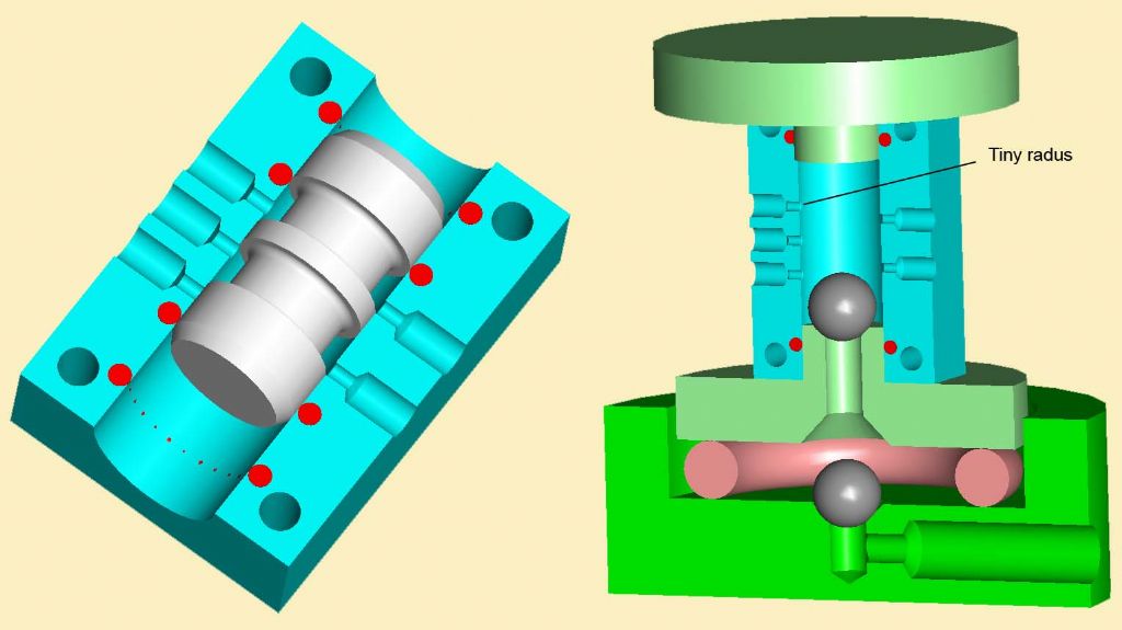 In my diagrams, you can see the basics of the valve, and the method I used to pump the tripoli slurry through the valve ports. The slurry was gravity fed into the bottom RH drilling, while the two balls controlled the direction of flow. However, while there are a couple of notes with this picture, I hesitate to go into specific detail unless anyone has additional questions.
Regards to all,
Sam
PS My skeleton clock is now running well with previous over-night errors of about 2 seconds per hour fast. After todays adjustment, the last (three-hour) time check, revealed an error which was too small to record against my computer clock. Edited By Sam Stones on 14/06/2011 06:03:21 |
| Sam Stones | 15/06/2011 09:44:34 |
922 forum posts 332 photos |
Thanks for your comments Michael. I agree with you about fluidics, and how it doesn’t seem to have established a place in technology. For companies into pneumatics, it was probably attractive in the early days, but I would assume that there are many more electronic switching solutions rather than adopting this method. I've seen (on TV) the results of using air lines to trigger lightening strikes through copper wire, but I imagine even this would not need sophisticated fluidics. I was rather fortunate in developing and succeeding with the plastics valve. Developing from a simple conversation with a friend in research, I went on to make quite a range of specialised laboratory equipment.
This `arm’ of my business was (for a while at least), becoming bigger than my involvement in plastics technology.
Regards, Sam |
| PekkaNF | 15/06/2011 15:10:50 |
| 96 forum posts 12 photos | Thank you Sam. I enjoyed the the diagram. I'll definately keep thin in my mind, because I sometimes have to come up with a cunning plan to avoid getting into too big pile of er...fluiddynamics. I have some small trough cooled tools. I'm thinkking of using an old espressomachine pump and if that does not work I probably have to make peristaltic pump. Small flow, but few bars are needed. Those fluid dynamic components were primary designed before to conditions where silicon based electronics didn't travel well. Like temperatures of few hundred decrees, nasty atmosphere, radiation, strong electromagnetic phenomenons...you'll get the drift. Models were made out of plastics, but real world stuff was different. Now, there are radiation hardened IC:s and some that will manage a little elevated temperature, that sort of ate their lunch. Pekka |

Please login to post a reply.
Magazine Locator
Want the latest issue of Model Engineer or Model Engineers' Workshop? Use our magazine locator links to find your nearest stockist!
Sign up to our Newsletter
Sign up to our newsletter and get a free digital issue.
You can unsubscribe at anytime. View our privacy policy at www.mortons.co.uk/privacy
Latest Forum Posts
- *Oct 2023: FORUM MIGRATION TIMELINE*
05/10/2023 07:57:11 - Making ER11 collet chuck
05/10/2023 07:56:24 - What did you do today? 2023
05/10/2023 07:25:01 - Orrery
05/10/2023 06:00:41 - Wera hand-tools
05/10/2023 05:47:07 - New member
05/10/2023 04:40:11 - Problems with external pot on at1 vfd
05/10/2023 00:06:32 - Drain plug
04/10/2023 23:36:17 - digi phase converter for 10 machines.....
04/10/2023 23:13:48 - Winter Storage Of Locomotives
04/10/2023 21:02:11 - More Latest Posts...
- View All Topics
Support Our Partners


Shopping Partners
Subscription Offer

Latest "For Sale" Ads
- Reeves** - Rebuilt Royal Scot by Martin Evans
by John Broughton
£300.00 - BRITANNIA 5" GAUGE James Perrier
by Jon Seabright 1
£2,500.00 - Drill Grinder - for restoration
by Nigel Graham 2
£0.00 - WARCO WM18 MILLING MACHINE
by Alex Chudley
£1,200.00 - MYFORD SUPER 7 LATHE
by Alex Chudley
£2,000.00 - More "For Sale" Ads...
Latest "Wanted" Ads
- D1-3 backplate
by Michael Horley
Price Not Specified - fixed steady for a Colchester bantam mark1 800
by George Jervis
Price Not Specified - lbsc pansy
by JACK SIDEBOTHAM
Price Not Specified - Pratt Burnerd multifit chuck key.
by Tim Riome
Price Not Specified - BANDSAW BLADE WELDER
by HUGH
Price Not Specified - More "Wanted" Ads...
Get In Touch!
Do you want to contact the Model Engineer and Model Engineers' Workshop team?
You can contact us by phone, mail or email about the magazines including becoming a contributor, submitting reader's letters or making queries about articles. You can also get in touch about this website, advertising or other general issues.
Click THIS LINK for full contact details.
For subscription issues please see THIS LINK.
Digital Back Issues


Donate

 Register
 Log-in
Model Engineer Magazine
- Percival Marshall
- M.E. History
- LittleLEC
- M.E. Clock

ME Workshop
- An Adcock
- & Shipley
- Horizontal
- Mill

Subscribe Now
- Great savings
- Delivered to your door

Pre-order your copy!
- Delivered to your doorstep!
- Free UK delivery!
All Forum Topics > General Questions > A plastic valve