Forum sponsored by:

Metal fatigue and clock making
Mild steel clock frame - how to overcome metal fatigue
| Clive Cassel | 19/12/2010 12:26:38 |
| 5 forum posts | I'm making a John Wilding 16th century style clock which requires a frame from 1/8" x 1" ms bar. The frame requires right angle bends in the plane of the steel bar. I have tried steel bar from two suppliers and both bars snapped at some point. The method in the handbook says:
"A saw cut is made to a depth of about three quarters of the thickness of the strip. The cut is now closed up by bending the strip ... A second saw cut is now made in the same position removing the metal which has been pinched together ...the cut is closed up by bending ... and the process is repeated until a right angle has been formed."
On each occasion the bar has snapped at the joint before completion. What to do?
Many thanks in anticipation
Clive Cassel
|
| David Clark 1 | 19/12/2010 12:28:12 |
 3357 forum posts 112 photos 10 articles | Hi There
Heat it to red hot and then bend it.
regards David
|
| Jeff Dayman | 19/12/2010 13:55:38 |
| 2356 forum posts 47 photos | You might consider mitre cutting four pieces, welding them, grind the welds out and radius the outside corner. If an inside rad is desired for looks, an infill piece with the right radius could be welded in also. Electric arc or MIG welding would be best for this, as the filler wire is the same material as the stock, for best (most invisible) appearance for later operations.
Another option would be to have a picture frame shaped part cut by laser, waterjet or flame, then clean up the machine-cut egdes with files and grinder.
For an antique look, you could heat up the parts in a fire a few times to red heat, which will blister the steel a little and round off the sharp edges, as well as soften and stress relieve the steel. In the 16th centrury the iron used for such a clock frame would certainly have been fire-worked and very ductile.
JD |
| Nicholas Farr | 19/12/2010 15:35:35 |
 3988 forum posts 1799 photos | Hi, another technique you could try is, once you have made your saw cut, you could use a three corner file and widen the saw cut out to a V shape of say about 95/100 degrees inclusive. This would have the same mitre effect that Jeff has mentioned.
Wrought Iron was probaly used in the 16th century, and like Jeff says it was more ductile and less prone to work hardening which will lead into cracking and snapping, which is what your MS is doing. Wrought Iron. is not very common off the shelf these days.
Regards Nick. Edited By Nicholas Farr on 19/12/2010 15:48:24 |
| Gordon W | 19/12/2010 16:11:50 |
| 2011 forum posts | I don't understand this, are you trying to bend across the 1" dimn. ? ie. cut 3/4" deep. If so mitre end and weld as said. If bending the 1/8" thickness can do it cold with a big vise and square block and hammer, can get a good sharp corner if needed. Wrought iron is not made anywhere in the world anymore, the last lot I got, 20 yrs. ago was some re-worked stuff from an industrial museum, but I would like to be proved wrong. |
| NJH | 19/12/2010 16:14:48 |
 2314 forum posts 139 photos |
Hi Clive
I think David has it right here. MS would bend fairly easily if you can get it to red heat - however I don't know what facilities you have for heat treatment. Whilst the welding method would, no doubt, achieve the desired shape it seems to me rather out of sympathy with 16th century clock making !
You could drop a mail to John Wilding ( via www.ritetimepublishing.com) and ask him for the source and spec.of his material.
Quite an interesting clock ( but not a reliable time - keeper I suspect!) . How about a few photos as you progress the project?
Regards
Norman
Edited By NJH on 19/12/2010 16:17:14 Edited By NJH on 19/12/2010 16:19:40 |
| Keith Long | 19/12/2010 17:01:03 |
| 883 forum posts 11 photos | Don't know about welding being out of sympathy, I'd have thought that forge welding it from strip was quite probably how they'd have done it back then. OK mma or mig wasn't around but it would be in a similar spirit. Quite possibly they'd use a combination of the two techniques, cut and bend and then hot forge the joint solid. Keith |
| Terryd | 19/12/2010 18:31:21 |
 1946 forum posts 179 photos | Hi Clive, Are you using bright drawn MS or black hot rolled bar? and when you say 'in the plane of the steel bar' I presume that you mean you are bending the 1" wide section so that the frame lies flat in that section, if you know what I mean. What radius is the bend? Is there a picture or diagram you could post? Terry PS I just reread your post after being sidetracked by another posting. I have found an image of the clock and see what you mean. Hot rolled bar is more malleable than bright drawn and David is correct in that if you can get localised red heat and use bending bars or similar in a vice you should be able to bend without saw cutting. That would be how a blacksmith would do it so is in the spirit of the original T Edited By Terryd on 19/12/2010 19:06:25 |
| macmarch | 19/12/2010 18:56:06 |
| 147 forum posts 1 photos | If you are not going to weld it, then I would suggest using the "black mild" stuff that B & Q sell. It brazes ok, machines to an acceptable finish and bends to quite a tight radius. It does need a little heat if bending tight. The surface coating splits off as you bend it.
I have checked with many sources for a ductile bending quality steel but it seems that there is no modern spec. unless someone knows better!
chhers
Ray |
| NJH | 19/12/2010 19:44:25 |
2314 forum posts 139 photos | Hi Keith
Yes on reflection you are quite right - forge welding was correct for those times. I guess I was distracted by reference to Arc & MIG welding - both black arts to me!
I the case of this clock however just a bit of heat to bend the steel is all that is required. As stated above though the black variety is the one to use.
Cheers
Norman
|
| Terryd | 19/12/2010 22:52:09 |
1946 forum posts 179 photos | Hi Norman,
The problem with bright drawn steel bar is that the outer skin is stressed and work hardened by the manufacturing process. By cutting 3/4 of the way through you are trying to bend a less malleable and ductile skin. Hence it cracks and fails. which is why we suggested black bar, it doesn't have the built in stresses and work hardening. But there are other interesting ways to make your frame. To make a really sharp right angle instead of bending you could try a dovetail.
In metal it can be made in a similar way to a wooden dovetail used in
furniture making and then silver soldered, and even soft solder will
give a very strong joint. Flux before assembly though. Also it doesn't need to be quite as accurate as a wooden variety as you'll see below. It can also be made to lock tightly together to make an equally strong joint without any further soldering etc and this would be quite an authentic method to use. In this latter method you cut the single tail and pins as before but a couple of mm too long.
The tail is made first and the pins marked from it as in woodworking
practice. The most important part is to file the shoulders accurately
and square, take great care over this. Now a secondary angle is filed in the vertical cut out of the pin,
undercutting them. The joint is assembled and the end of the tail is
peened so that the material is forced to fill the 'undercuts' in the
pins, locking and securing the assembly. The pins can also be peened in
thus taking up any inaccuracy and the excess material filed and tidied
up. It almost takes longer to describe than do. The only tools you
need are a junior hacksaw, 3 square file, a ball peen hammer and a vice
(and basic marking out tools of course). I've included a few diagrams below to try to illustrate better what I mean. It's worth trying on some of your scrap and it can be done with the material you already have. 1: Typical plain dovetail ready for soldering: 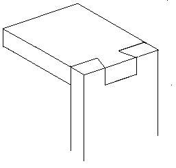 2 Alternative method with no soldering etc needed - Pins formed by sawing and filing, then a secondary angle is filed as indicated by the shaded areas to undercut the pins: 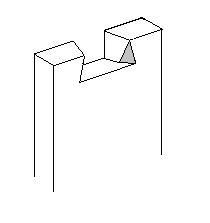 3: Joint assembled showing gaps caused by undercutting pins: 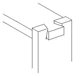 4: Final Joint. Tail has been peened to force material into gaps (shaded areas) thus making the joint rigid and secure without soldering or welding. 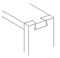 Terry Edited By Terryd on 19/12/2010 23:00:28 |
| Keith Long | 19/12/2010 22:59:32 |
| 883 forum posts 11 photos | Hi Terry I like that idea - seems right and "country-style" somehow. If you had a bit of relief filed on the upper edges of the "tail" you could swage the pins over as well make it virtually impossible to pull apart. If they could build the "Ironbridge" with "woodworking" joints a clock should certainly work. Keith |
| Terryd | 19/12/2010 23:25:04 |
1946 forum posts 179 photos | Hi Keith,
Even with the method I've outlined the joint cannot be
pulled apart as you have a double wedge effect. It really makes a
strong joint. Of course the joint can be milled using a dovetail cutter
but I like to make it with saw and file, it's a bit more challenging.
It's a very old technique and the old blacksmiths would cut the joints
quite roughly with a chisel on hot material and forge. it together wile
red hot. Also to improve the look and make it more decorative, the pins
and tail would not be filed down, instead they would be planished when
cold with the round peen of the hammer to give a rounded 'hammered' look similar to a coppersmith on fire hoods and table tops etc. Properly done it is a very decorative and authentic method of this type of joint. I use the soldered variety for making upstands for some of my small oscillating steam engines. It makes a change from rivets and belongs to a time before screw threads were invented. I only file the shoulders of the joint. I try to leave the other cuts as sawn as when planishing, the material is forced into the marks left by the saw, strengthening the joint. By the way, it was also used by the old
woodworking plane makers in the time between the wooden plane and the
modern cast body plane. The plate sides would be attached to the sole using rows of dovetails and then this body infilled with decorative hardwoods with brass and steel fittings. They were works of art. If you look very carefully you can just about make out the dovetails joining the side plate to the sole on this example. 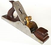 Edited By Terryd on 19/12/2010 23:39:18 |
| Terryd | 19/12/2010 23:32:22 |
1946 forum posts 179 photos | Hi There, Sorry to hog the thread but my first post on the dovetails should have been addressed to Clive rather than Norman, blame the late hour (no alcohol to use as an excuse either). I apologise for the mistake. Terry |
| John Olsen | 20/12/2010 06:47:42 |
| 1294 forum posts 108 photos 1 articles | Now that the original problem has been pretty well dealt with, can I put on pedantic mode for a moment and mention that the original fractures had nothing to do with fatigue. They would be a normal fracture caused by stressing the material past its elastic limit, and would have the typical chrystalline appearance of such a fracture. I don't know if modern theories have changed, but our mechanics and strength of materials lecturer made a distinction between fatigue, as commonly seen in materials like aluminium, and crack propagation, as often seen in highly stressed components like steel connecting rods. The way he explained it, fatigue occurs with loads that reverse, and the time it takes for it to become significant depends on the magnitude of the load and the number of load reversals. So far as was known at that time, there was no lower limit although with a small enough force the number of reversals required would require such a long time that it could never actually be acheived. Not all materials are prone to this type of fatigue, aluminium of course being the classic example. One of his examples slides was a photograph of a wing spar from a Bristol freighter that failed in the air over Christchurch (NZ) The effect of fatigue of this sort is that otherwise strong enough material loses its strength, and cracks will begin to grow, leading to failure. The only way to avoid this process is to keep a record of the usage, and discard the component when it has reached a known maximum safe life. On the other hand, according to him, crack progagation can occur in pretty well any material that is not too ductile. If the material is very ductile it will just give a little at the stress concentration, releiving the local stress without extending the crack. With less ductile material a microcrack can grow at a local stress concentration and keep growing each time the stress peaks, eventually getting long enough that failure occurs. Because the mechanism is different, it is possible to stave off the begining of this process by means like polishing the surface, to remove stress concentrators like scratches. Also you can test a used component, and if no cracks have started you can reuse it, as used to often be done with connecting rods. Of course, with either mechanism once the cracks have got going, the end result is inevitable and predictable, and the resulting appearance of the failure is likely to be similar. So what I am curious to know, if there are real metallurgists here, is this distinction still made? Or was it just a bee in the bonnet of that particular lecturer? regards John |
| Terryd | 20/12/2010 08:59:12 |
1946 forum posts 179 photos | Hi John, No one has mentioned 'fatigue', but we have mentioned work hardening. This occurs when any metal is stressed by physical means, whether that is fatigue caused by load reversal in aircraft spars or in con rods, or distortion by hammering into shape etc. I'm no metallurgist but I seem to remember from my Mat. Sci. lecturers that any work hardening distorts the crystals in the metal. As they are distorted the atomic bonds are stretched and become less able to become further distorted so the grain boundary between the crystals become more distorted and stressed as they have to sustain more distortion with further working. And it is the grain boundary , not the crystal which fails (the atomic bonds in the crystal are too strong to fail under normal loads) as it has become distorted and over stressed. This then increases the strain (and stress) on the remaining boundaries, the process is accelerated and the material eventually fails, final failure occurring suddenly as many boundaries fail quickly. This was epitomised (exemplified?) by the failure of an overhead walkway in a shopping mall in the USA when the supporting rods failed due to over stressing caused when the builder deviated from the design ( a case of a craftsman thinking he knew better than the designer!). Quite a number of people were killed. If we normalise the component with heat , the heat relaxes the crystal boundary and the slow rate of cooling allows the crystals to relax into their original form. and the stresses in the grain boundary reduced (or removed). Of course if we overheat the metal the grain boundaries become so relaxed that they allow the crystals to flow and the metal enters it's liquid phase. As Bright bar is drawn down through the dies, the surface of the bar becomes work hardened due to the crystals becoming deformed during the process. There is less distortion in the centre and there is an inbalance in stress concentration at the grain boundaries through the material, hence when machining Bright drawn bar it is best to remove equal amounts from opposite surfaces in order to balance the stresses otherwise distortion of the machined component can occur. In Clive's clock he is cutting through the bar leaving only about 0.8 mm of material to bend and if he is using bright bar which is not normalised he is trying to bend the most highly work hardened and stressed part of the bar. hence the grain boundaries will fail at the outer surface thus propagating a crack and finally inevitable failure. I believe that your lecturer was correct in saying that cracks can be propagated at stress concentration points like scratches and other faults when a metal component is loaded, even with a constant unchanging load and that these can be minimised by polishing to remove or reduce such faults, but that is not the only situation where cracks can begin. Now I am sure that someone with more knowledge than myself will be able to shoot me down and add to the debate. By the way John, it is a treat to see someone who can structure a piece of writing using proper paragraphs.  Regards Terry |
| RJW | 20/12/2010 10:25:31 |
| 343 forum posts 36 photos | Terryd, re: Fatigue, it Was mentioned actually, please refer to the actual topic heading! Great thread all the same. Regards, John |
| Gordon W | 20/12/2010 10:26:04 |
| 2011 forum posts | Still can't find the original drawings, but- corners like these, in the olden days, were often made by upsetting the ends and forming into 90deg. "brackets", then riveting onto flat pieces. An easier modern way is to make the saw cut on the outside of the bend, then weld, makes a neat joint. The old fire welding blacksmiths would have used electric welding if they had the chance. Sorry not properly formed para. but have found the spell -check button. |
| Terryd | 20/12/2010 10:39:55 |
1946 forum posts 179 photos | Hi RJW, Of course you are correct and I apologise to John Olsen if I have contradicted anything he said, I was just trying to extend his excellent contribution. Hi Gordon, Only one paragraph needed, . Best regards and seasons greetings, (we need a holly icon in the smileys!!) Terry Edited By Terryd on 20/12/2010 10:41:49 |
| Ian S C | 20/12/2010 11:39:04 |
 7468 forum posts 230 photos | As an aircraft engineering apprentice i was very soon told the reason for not using "Aviation Snips", invented before the war in America, and after a while the began to wonder why aeroplanes/ airplanes were falling out of the sky, if you look at aviation snips you will see that the edge is finely serrated, thats the answer.
One of our instructors at NAC (now Air New Zealand) was on the next green , on the golf course when the 10,000 pop rivits ceased to be flying in close formation, as the Freighter crashed he was one of the first on site. The aircraft was designed toward the end of the war, and was virtually a powered replacement for the transport gliders, and giving components a life in hours flown was not thought necessary, disposable aeroplane. They actually gave good service.
On our Cessna aircraft we had a number of fatigue problems, the Cessna 185, a tail dragger used to break the tail spring (to which the tail wheel is attached), some one came up with a stronger one, but none of the pilots would fly a plane with it fitted, they said rather the spring breaks, that the tail falls off. Ian S C |
Please login to post a reply.
Magazine Locator
Want the latest issue of Model Engineer or Model Engineers' Workshop? Use our magazine locator links to find your nearest stockist!
Sign up to our Newsletter
Sign up to our newsletter and get a free digital issue.
You can unsubscribe at anytime. View our privacy policy at www.mortons.co.uk/privacy
Latest Forum Posts
- hemingway ball turner
04/07/2025 14:40:26 - *Oct 2023: FORUM MIGRATION TIMELINE*
05/10/2023 07:57:11 - Making ER11 collet chuck
05/10/2023 07:56:24 - What did you do today? 2023
05/10/2023 07:25:01 - Orrery
05/10/2023 06:00:41 - Wera hand-tools
05/10/2023 05:47:07 - New member
05/10/2023 04:40:11 - Problems with external pot on at1 vfd
05/10/2023 00:06:32 - Drain plug
04/10/2023 23:36:17 - digi phase converter for 10 machines.....
04/10/2023 23:13:48 - More Latest Posts...
- View All Topics
Support Our Partners


Shopping Partners
Subscription Offer

Latest "For Sale" Ads
- Reeves** - Rebuilt Royal Scot by Martin Evans
by John Broughton
£300.00 - BRITANNIA 5" GAUGE James Perrier
by Jon Seabright 1
£2,500.00 - Drill Grinder - for restoration
by Nigel Graham 2
£0.00 - WARCO WM18 MILLING MACHINE
by Alex Chudley
£1,200.00 - MYFORD SUPER 7 LATHE
by Alex Chudley
£2,000.00 - More "For Sale" Ads...
Latest "Wanted" Ads
- D1-3 backplate
by Michael Horley
Price Not Specified - fixed steady for a Colchester bantam mark1 800
by George Jervis
Price Not Specified - lbsc pansy
by JACK SIDEBOTHAM
Price Not Specified - Pratt Burnerd multifit chuck key.
by Tim Riome
Price Not Specified - BANDSAW BLADE WELDER
by HUGH
Price Not Specified - More "Wanted" Ads...
Get In Touch!
Do you want to contact the Model Engineer and Model Engineers' Workshop team?
You can contact us by phone, mail or email about the magazines including becoming a contributor, submitting reader's letters or making queries about articles. You can also get in touch about this website, advertising or other general issues.
Click THIS LINK for full contact details.
For subscription issues please see THIS LINK.
Digital Back Issues


Donate

 Register
 Log-in
Model Engineer Magazine
- Percival Marshall
- M.E. History
- LittleLEC
- M.E. Clock

ME Workshop
- An Adcock
- & Shipley
- Horizontal
- Mill

Subscribe Now
- Great savings
- Delivered to your door

Pre-order your copy!
- Delivered to your doorstep!
- Free UK delivery!
All Forum Topics > Beginners questions > Metal fatigue and clock making