Forum sponsored by:

Dynamo/generator.
| Paul Clapham | 26/10/2010 20:15:20 |
 19 forum posts 1 photos | Hi
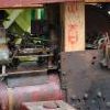
Can any one shed any light on this generator, where it might have been used and the correct way to wire it up?
At the moment if I put 12 volts in on the left hand side (brown) which will run the unit, and get 100 volts out on the right (red/yellow) on the side of the unit there are two more voltages 265v and 530v.
I have another unit as well (see other photo) which I need help with.
Cheers Paul. |
| Stub Mandrel | 26/10/2010 20:34:30 |
 4318 forum posts 291 photos 1 articles | I can't for the life of e remember what that's called, but essentially it's what used to be used befoire the solid state inverter, to create 'high tension' supplies for things like radios in military vehicles. Neil |
| Billy Mills | 26/10/2010 20:37:36 |
| 377 forum posts | Paul, You have a rotary convertor, around WW2 vintage. It was used to generate the voltages needed for valved electronic equipment in a car, lorry or tank. From the voltages would suggest a transmitter or radar equipment. It is a 12V motor with extra windings and commutators-but no drive shaft. As the motor spins the secondary windings see a changing magnetic field that induces the higher voltage in the secondary coils. Millions of these things were made in WW2. With the advent of transistors rotary convertors became obsolete. regards, Alan |
| John Haine | 26/10/2010 20:38:58 |
| 5563 forum posts 322 photos | What more is there to say? It's a motor/generator as made around WW2 time to produce a HV dc output from the 12 V from a vehicle battery to run military radios. You wire it up to 12 volts on one side, it whizzes away and produces 100/265/539 V on the other. Radios would run the tuve heaters from 12 volts and use the HV for the plate supply. If you wanted to do this today a solid state dc/dc converter would be much cheaper, quieter, and more reliable. When I got first interested in electrical things are around age 10 (in 1960) the ad pages of Wireless World were full of this stuff usually selling at 12/6d. |
| Andrew Johnston | 26/10/2010 20:42:23 |
 7061 forum posts 719 photos | Motor-generator set, shortened to M-G set? Regards, Andrew Edit: Ah well, beaten to it! Edited By Andrew Johnston on 26/10/2010 20:43:31 |
| john swift 1 | 26/10/2010 20:45:28 |
 318 forum posts 183 photos | rotory converters or " dynamotor " like that was used during WW2 and after to provide the ht supplies
for valve equipment used by the armed forces
the 500v ht would be ideal for the PA (output ) stage of a transmitter
basically its a combined motor and dc generator with a common field winding
as you will of descovered
i've not used one my self so I don't have have any detail to hand
eg the number 62 set used one
John
Edited By john swift 1 on 26/10/2010 21:02:36 Edited By john swift 1 on 26/10/2010 21:06:22 |
| Nicholas Farr | 26/10/2010 23:19:33 |
 3988 forum posts 1799 photos | Hi, I do believe they were from WW2 era. My farther had one very similar and I think he said it was somthing used for old radio's before the National Grid, as local ES was DC then. Never did know how is was wired though.
Regards Nick. |
| John Olsen | 27/10/2010 05:18:34 |
| 1294 forum posts 108 photos 1 articles | I get the impression that he has actually got the wiring right anyway, you put 12 volts in and you get the high voltages out. I beleive some of the aircraft ones were for 28 volts in. I can't think of much practical use for one these days, but someone who is into vintage wireless might be pleased to get one. They could in theory be used for a motor, but are much bulkier for the power you would get than a normal motor would be, especially a modern permanent magnet motor. They also don't provide a shaft to connect onto. regards John |
| Ian S C | 27/10/2010 08:23:33 |
 7468 forum posts 230 photos | Had a look at the photos in the album ,no.1 could be used as a generator, its proberbly got a good output watt wise.
Back in the 60s when I started in agricultural aviation we were just getting rid of the American military(ww2) ARC-5 radios (they weighed tons), an they had genimotors in them, ours were changed from 28V to 12V. We changed from some thing that was about a 2ft cube+ the remote control unit, to a bit bigger than a normal car radio, a locally made transistor transciever. These radios were in Cessna 180/185 aircraft.
12-15 landings an hour in a 12 hour working day on rough farm airstrips was rather hard on valve radios, plus the radio took over 100lb of the pay load. Ian S C |
| Geoff Theasby | 27/10/2010 08:57:18 |
| 615 forum posts 21 photos | I still have a complete power supply using US versions of these.
I am reluctant to part with it because, whatever you may think of the light weight and silent operation of transistor inverters, dynamotors are 100% reliable.
Of course, modern mobile radio equipment is all-transistor, and there is no need of inverters. But when the oil crisis strikes... |
| Gordon W | 27/10/2010 12:04:15 |
| 2011 forum posts | Had one similar years ago. In our ignorance just wired one end to a car battery, other end would run Wolf drill or similar, (no mains then). Also converted one to a grinder, can't remember how, but worked ok. |
| Paul Clapham | 27/10/2010 15:08:18 |
19 forum posts 1 photos | Fantastic response thank you for that, this one I have managed to get to work and it works well. I have another one which has a shaft sticking out of one end and no matter what configuration of wiring I come up with I get nothing, the windings all seem fine and the brushes are good I have cleaned the coms up with fine sandpaper.
The second one I was hoping to use as a dynamo on a showmans traction engine that I am rebuilding.
Once again thanks to everyone.
Paul. |
| Chris Kelland | 27/10/2010 18:15:33 |
| 10 forum posts | Hi Paul, Don't use any sort of abrasive on the com copper filings will get in the segments and cause shorts. Just use meths to clean the dirt off. What you have is a rotary transformer. It allows mains powered AC to be used mobile, usually RT sets. 2 windings, or more on the armature and only one field winding. Not a lot of use for anything else due to DC output. Rotary converters were much more useful, same idea but with slip rings instead of a commutator giving AC instead. As an apprentice the firm I worked for had several of these used to run PA systems where no mains supply was available. A variety of DC inputs, usually 12 or 24 volts and according to the state of the batteries from around 200 to 230 volts output. The ones I used were rated at 250 watts, so a bit heavy and chunky but very reliable and quiet. Chris. |
| Ian Abbott | 27/10/2010 19:51:02 |
 279 forum posts 21 photos | On old stuff like this, we'd check for open circuits on the commutator or where the segments had shorted out between the segments.
If the windings were okay, we'd spin the armature up in a lathe and either clean the comm. up with emery, or if the wear was too bad, turn it down to a good surface then polish with abrasive.
This would invariably burr one segment over onto the next, so we would then undercut the segments into the insulation with a fine hacksaw blade with tape as a handle.
I think that there was a proper undercut tool, but we had broken hacksaw blades a plenty.
Ian |
| John Olsen | 27/10/2010 20:07:50 |
| 1294 forum posts 108 photos 1 articles | Well, as somebody else already said, abrasives, particualrly emery, are not really the done thing on commutators. The use of a broken hacksaw blade to clear back the Mica from between the segments seems to be the standard approach, at least everything I have seen on the subject has had a little diagram of how to grind one end of the blade to make a suitable cutter. I am not sure that I agree with the "100% reliable" bit, we would not be talking about how to clean up commutators if they never gave trouble. The modern transistor one, at least if from a reputable supplier, probably has a much longer mean time between failures. However, when it does give trouble, you need access to the right spares, while you could generally recondition a dynamotor with a pretty ordinary workshop. When I was about so high, my Dad took me along on a visit to the power station for the trolley buses that they had at that time here in Auckland. This had previously been the power station for the tram cars. They did not generate their own power, at least not as far as I can recall, but they had three generations of equipment for turning AC mains into DC for the overhead wires. First was rotary convertors, giant versions of what we see above, although built more in the old style, eg a very large diameter relative to the length. Next was mercury arc rectifiers, one of which is actually still operational now at our transport museum at Western Springs, driving the trams there. Finally they had some of the then newfangled and high tech silicon rectifiers. All of these were still in use at the same time. I am not sure now if the silicon rectifiers were just straight diodes, or if they were SCRs. (Thyristors to some) regards John |
| Paul Clapham | 28/10/2010 14:22:11 |
19 forum posts 1 photos | Once again thank you all for that I have learned a lot from your input.
Best regards
Paul. |
| KWIL | 28/10/2010 14:30:52 |
| 3681 forum posts 70 photos | Do not ever use emery as the abrasive can embed itself into the copper. But as John Olsen says, do clean out the gaps between the com bars, trying not to raise an edge which would defeat the objective of smoothing it. |
| Billy Mills | 28/10/2010 14:41:48 |
| 377 forum posts | Here's a twist in the story. The Dynamotor did not normally have an output shaft and is truly obsolete, it is heavy, the brushes wear out, it is noisy electrically-needs "hash"filters and takes up a lot of space. You might find a motor with two sets of brushes - one at each end and two commutators. It is a servomotor with built in tacho generator. One set of windings are low resistance for the motor, the other windings are much thinner wire wound in the same slots. Sometimes the larger versions use seperate short slots for the tacho rotor windings. The integral tacho provides a direct voltage proportional to rotor speed with polarity indicating direction of rotation. When used with a good bipolar servo amp you can get a very high performance servo loop. Regards, Alan. |
Please login to post a reply.
Magazine Locator
Want the latest issue of Model Engineer or Model Engineers' Workshop? Use our magazine locator links to find your nearest stockist!
Sign up to our Newsletter
Sign up to our newsletter and get a free digital issue.
You can unsubscribe at anytime. View our privacy policy at www.mortons.co.uk/privacy
Latest Forum Posts
- *Oct 2023: FORUM MIGRATION TIMELINE*
05/10/2023 07:57:11 - Making ER11 collet chuck
05/10/2023 07:56:24 - What did you do today? 2023
05/10/2023 07:25:01 - Orrery
05/10/2023 06:00:41 - Wera hand-tools
05/10/2023 05:47:07 - New member
05/10/2023 04:40:11 - Problems with external pot on at1 vfd
05/10/2023 00:06:32 - Drain plug
04/10/2023 23:36:17 - digi phase converter for 10 machines.....
04/10/2023 23:13:48 - Winter Storage Of Locomotives
04/10/2023 21:02:11 - More Latest Posts...
- View All Topics
Support Our Partners


Shopping Partners
Subscription Offer

Latest "For Sale" Ads
- Reeves** - Rebuilt Royal Scot by Martin Evans
by John Broughton
£300.00 - BRITANNIA 5" GAUGE James Perrier
by Jon Seabright 1
£2,500.00 - Drill Grinder - for restoration
by Nigel Graham 2
£0.00 - WARCO WM18 MILLING MACHINE
by Alex Chudley
£1,200.00 - MYFORD SUPER 7 LATHE
by Alex Chudley
£2,000.00 - More "For Sale" Ads...
Latest "Wanted" Ads
- D1-3 backplate
by Michael Horley
Price Not Specified - fixed steady for a Colchester bantam mark1 800
by George Jervis
Price Not Specified - lbsc pansy
by JACK SIDEBOTHAM
Price Not Specified - Pratt Burnerd multifit chuck key.
by Tim Riome
Price Not Specified - BANDSAW BLADE WELDER
by HUGH
Price Not Specified - More "Wanted" Ads...
Get In Touch!
Do you want to contact the Model Engineer and Model Engineers' Workshop team?
You can contact us by phone, mail or email about the magazines including becoming a contributor, submitting reader's letters or making queries about articles. You can also get in touch about this website, advertising or other general issues.
Click THIS LINK for full contact details.
For subscription issues please see THIS LINK.
Digital Back Issues


Donate

 Register
 Log-in
Model Engineer Magazine
- Percival Marshall
- M.E. History
- LittleLEC
- M.E. Clock

ME Workshop
- An Adcock
- & Shipley
- Horizontal
- Mill

Subscribe Now
- Great savings
- Delivered to your door

Pre-order your copy!
- Delivered to your doorstep!
- Free UK delivery!
All Forum Topics > Beginners questions > Dynamo/generator.