Forum sponsored by:

Making Tapered Castellations in Aluminium
| Dr_GMJN | 11/08/2021 13:16:21 |
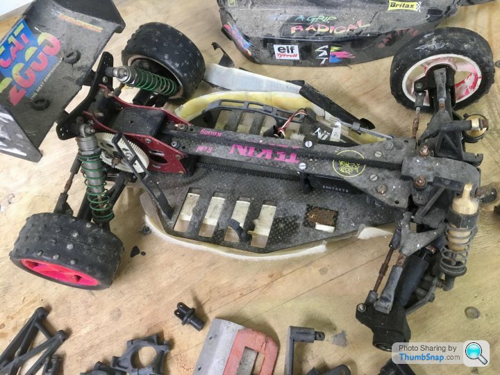
 1602 forum posts | All, my son was given an old - and very knackered - Schumacher R/C car to rebuild as an engineering project: |
| JasonB | 11/08/2021 13:23:17 |
 25215 forum posts 3105 photos 1 articles | Should be easy enough to mill with the spigot stood vertically, cut one side of a "tooth" rotate and cut the other. Off out now but will post later if you don't get a better answer |
| Tony Pratt 1 | 11/08/2021 13:28:21 |
| 2319 forum posts 13 photos | Have you got a milling machine & rotary table? Tony |
| Andrew Johnston | 11/08/2021 13:31:16 |
 7061 forum posts 719 photos | The existing parts don't look like they've got a taper on the teeth. Machining straight-sided teeth is a simple operation involving a rotary table to machine the sides of each tooth in turn. If a taper really is needed, simply tilt the head of the mill, or the rotary table. Aluminium seems an odd choice of material. Steel would be better wearing and less prone to fatigue. Andrew |
| Dr_GMJN | 11/08/2021 13:42:51 |
1602 forum posts | Sorry guys I didn't explain that very well. Edited By Dr_GMJN on 11/08/2021 13:43:27 |
| Gary Wooding | 11/08/2021 14:20:31 |
| 1074 forum posts 290 photos | How about a jeweller's piercing saw? |
| An Other | 11/08/2021 14:24:04 |
| 327 forum posts 1 photos | Looking at your photo of the castellations, would it not be possible to use a fine saw and cut straight across the end (e.g from 10 o'clock to 4 o'clock hope that makes sense), and similarly with the other flanks of the 'teeth', then use a small drill to remove the bulk of the metal from between the sawcuts, and finish off to size with a needle file? |
| Michael Gilligan | 11/08/2021 14:36:01 |
 23121 forum posts 1360 photos | Posted by Dr_GMJN on 11/08/2021 13:42:51:
[…]
. For parts on that scale, with only a few divisions … It should be possible to cobble-together some sort of dividing contraption. MichaelG. |
| pgk pgk | 11/08/2021 14:39:25 |
| 2661 forum posts 294 photos | As Jason and others say it is simple enough with a rotary table to cut the parallel paths then rotate the table and offset to cut each side of each castellation to the taper pgk |
| Andrew Johnston | 11/08/2021 14:45:54 |
7061 forum posts 719 photos | Given that the sides of the wedges are radial lines all that is needed is to offset the cutter by half its diameter, away from the wedge, while indexing round each tooth with the rotary table and the wedge shapes will appear. Opposing sides of the wedges need equal, but opposite, offsets. Each cut only goes to the centre, not across the diameter. I expect Jason will knock out a quick Alibre drawing to show the method. Andrew |
| Mick B1 | 11/08/2021 14:49:18 |
| 2444 forum posts 139 photos | Would a thin (say 0,75mm or 1/32" ) slitting saw pass below the southern edge of the eastern merlon and above the northern edge of the western one in the above pic? If so, you could use the sawcuts as flank markers for end milling out the crenels. If you have a swivel vice you could presumably calculate and set the angles. You might have to finish with a Swiss file, Dremel or suchlike. Edited By Mick B1 on 11/08/2021 14:50:19 |
| Peter Cook 6 | 11/08/2021 14:52:40 |
| 462 forum posts 113 photos | Do they need to be tapered. I would guess from a power transmission point of view they will be well over engineered. A suggestion might be to modify the existing stub axles to simplify things.
Mill the existing outboard pieces as per the bottom diagram to remove the red bits. It's four straight cuts (two "vertical, two "horizontal) with a small milling cutter. Then make the new components to the top design. This time only two cuts straight across. Without dimensions, I don't know what size cutters you might need, but if the gaps between the teeth in the centre are 1.6mm then a 1mm cutter will probably suffice.
PS thanks for the question, solving your problem has made me think again about the design of adog clutch I have made. Edited By Peter Cook 6 on 11/08/2021 14:57:24 |
| Dr_GMJN | 11/08/2021 15:06:33 |
1602 forum posts | Can anyone recommend a rotary table then for an SX2P Mill? Like I said I've not got one, but it would be a nice toy to play with and then it's a simple matter with a 1.5 mm diameter milling cutter. |
| Andrew Johnston | 11/08/2021 15:29:59 |
7061 forum posts 719 photos | Posted by Dr_GMJN on 11/08/2021 15:06:33:
Can anyone recommend a rotary table then for an SX2P Mill? Not specifically as I'm not familiar with the mill, but offer the following points for consideration:
To illustrate the points, here's a horizontal setup:
Note the central rod; simply stock bar with a 1" spigot turned on the end. The clamps under the gear only just fit on the table. And a vertical setup:
Andrew |
| John Hinkley | 11/08/2021 15:35:59 |
 1545 forum posts 484 photos | Not having a rotary table is a bit constricting, but not insurmountable. In your position I would either make it from square stock and use the sides to do the indexing, against a vice stop and turn it down afterwards or make it out of round stock with a stub on the "back". Drill and/or bore a central hole in the aforementioned square stock, securing it with a grub screw or just superglue. Mount the square stock vertically in the mill vice and proceed to mill as described in previous posts. A rotary table will be a useful addition to your workshop and I would suggest a 4"/100 mm one, preferably with division plates. John |
| Michael Gilligan | 11/08/2021 15:49:41 |
23121 forum posts 1360 photos | Posted by Dr_GMJN on 11/08/2021 15:06:33:
Can anyone recommend a rotary table then for an SX2P Mill? Like I said I've not got one, but it would be a nice toy to play with and then it's a simple matter with a 1.5 mm diameter milling cutter. . That's fine ... new toys are always fun ... ignore my suggestion MichaelG. |
| JasonB | 11/08/2021 16:11:34 |
25215 forum posts 3105 photos 1 articles | You don't really need a rotary table for that, infact you could do it by just rotating the part once, either way a simple printed out paper disc and pointer would do. First thing is to look at the part and asses how it can be machined, simply by rotating slightly you will see that the radial faces can be lined up with the X and Y planes.
A bit of CAD to draw out teh shape, I've assumed a 5mm hole and shown your 1.6mm gap. Which a 1.5mm dia cutter will just fit through so offset by half cutter dia and machine one face, probably go down in 0.5mm steps
This will leave your part looking like this
You can either leave it in the same position and make another cut in X coming in from the right and offset 0.75mm below the x axis then two cuts from top and bottom either side of teh Y axis. Or if tooling permits rotate 90deg and make a cut repeat twice. You will end up with 4 slots forming 4 of teh dog faces
Now rotate the work by the complimentry angle of the 37.05deg, offset below X axis and make a cut.
Which and then do it three more times by rotating 90deg or cutting in teh other three axis and part will then look like this
Edited By JasonB on 11/08/2021 16:18:40 |
| JasonB | 11/08/2021 17:03:29 |
25215 forum posts 3105 photos 1 articles | As a rule of thumb I would say go for a rotary table approx the siz eof the mills table front to back so maybe 5" diameter. My reason being that with limite dhead room on some of the bench mills you can soon run out of head room particularly if teh table is vertical. This is how the SX2.7 is set up at the moment from rounding a couple of rod ends. 6mm dia cutter sticking out no more than 20mm from the collet. yet there is only 1" of vertical movement left in the head as the 150mm R/T (larger than table size) and 5" chuck stack up.
Also a little video of the progression of the cuts to form your dog clutch |
| duncan webster | 11/08/2021 19:06:07 |
| 5307 forum posts 83 photos | Get a suitable size bit of square bar, machine spike on it to locate the bore of your castellated thing, then you can grip this in the machine vice and use it to index pretty accurately. Or even easier make it from square bar, finally turn it round after you've done the teeth Edited By duncan webster on 11/08/2021 19:09:14 |
| Brian H | 11/08/2021 19:13:00 |
 2312 forum posts 112 photos | Could the mating parts be made from an epoxy putty, presssed into the existing parts after putting some grease on the original part? Brian |


![20210811_163857[1].jpg](/sites/7/images/member_albums/44290/897780.jpg "20210811_163857[1].jpg")
Please login to post a reply.
Magazine Locator
Want the latest issue of Model Engineer or Model Engineers' Workshop? Use our magazine locator links to find your nearest stockist!
Sign up to our Newsletter
Sign up to our newsletter and get a free digital issue.
You can unsubscribe at anytime. View our privacy policy at www.mortons.co.uk/privacy
Latest Forum Posts
- *Oct 2023: FORUM MIGRATION TIMELINE*
05/10/2023 07:57:11 - Making ER11 collet chuck
05/10/2023 07:56:24 - What did you do today? 2023
05/10/2023 07:25:01 - Orrery
05/10/2023 06:00:41 - Wera hand-tools
05/10/2023 05:47:07 - New member
05/10/2023 04:40:11 - Problems with external pot on at1 vfd
05/10/2023 00:06:32 - Drain plug
04/10/2023 23:36:17 - digi phase converter for 10 machines.....
04/10/2023 23:13:48 - Winter Storage Of Locomotives
04/10/2023 21:02:11 - More Latest Posts...
- View All Topics
Support Our Partners


Shopping Partners
Subscription Offer

Latest "For Sale" Ads
- Reeves** - Rebuilt Royal Scot by Martin Evans
by John Broughton
£300.00 - BRITANNIA 5" GAUGE James Perrier
by Jon Seabright 1
£2,500.00 - Drill Grinder - for restoration
by Nigel Graham 2
£0.00 - WARCO WM18 MILLING MACHINE
by Alex Chudley
£1,200.00 - MYFORD SUPER 7 LATHE
by Alex Chudley
£2,000.00 - More "For Sale" Ads...
Latest "Wanted" Ads
- D1-3 backplate
by Michael Horley
Price Not Specified - fixed steady for a Colchester bantam mark1 800
by George Jervis
Price Not Specified - lbsc pansy
by JACK SIDEBOTHAM
Price Not Specified - Pratt Burnerd multifit chuck key.
by Tim Riome
Price Not Specified - BANDSAW BLADE WELDER
by HUGH
Price Not Specified - More "Wanted" Ads...
Get In Touch!
Do you want to contact the Model Engineer and Model Engineers' Workshop team?
You can contact us by phone, mail or email about the magazines including becoming a contributor, submitting reader's letters or making queries about articles. You can also get in touch about this website, advertising or other general issues.
Click THIS LINK for full contact details.
For subscription issues please see THIS LINK.
Digital Back Issues


Donate

 Register
 Log-in
Model Engineer Magazine
- Percival Marshall
- M.E. History
- LittleLEC
- M.E. Clock

ME Workshop
- An Adcock
- & Shipley
- Horizontal
- Mill

Subscribe Now
- Great savings
- Delivered to your door

Pre-order your copy!
- Delivered to your doorstep!
- Free UK delivery!
All Forum Topics > Workshop Techniques > Making Tapered Castellations in Aluminium