Forum sponsored by:

How could I make this curved conrod?
| SillyOldDuffer | 06/10/2017 16:49:59 |
| 10668 forum posts 2415 photos | This item is the con-rod for a model mill steam engine. I'm trying to make it properly as per plan.
The rod part of the con-rod is of circular section and the whole is curved on a 300mm radius. The rod is ⌀4mm at the ends and it bellies out to ⌀6mm in the middle. In a full size engine this is done to minimise the weight of the rod whilst keeping it stiff enough not to kink under compression. My problem is that I don't how to turn that R300 radius along the rod. I have a manual lathe. The curve implies that the tool point has to smoothly move in - out - in as well as from right to left. I prefer not to approximate the shape with tapers because that's not what the specification calls for. Can anyone help please? Thanks, Dave |
| Phil H1 | 06/10/2017 17:11:48 |
| 467 forum posts 60 photos | Dave, I have done this before (no pictures sorry) as follows (describing the central section only); 1. Turn the centre of the rod to 6mm diameter along its full length. 2. Use the top slide set at a shallow angle to turn a slight taper in one direction. 3. Reverse the rod (assuming you are turning between centres) to turn an identical, slight taper in the opposite direction. The end of the taper would achieve the 4mm diameter - or close to it at both ends. 4. Blend the tapers/ short parallel central section by using flat files. 5. Once the file work has blended the rod to a smooth curve, use progressive grades of emery cloth to complete the rod to a nicely polished finish. I understand that you are trying to work as accurately as possible (by quoting the 300mm radius) but I doubt if anyone will check it.
Hope that helps. Phil H |
| Jeff Dayman | 06/10/2017 17:12:46 |
| 2356 forum posts 47 photos | 1. I suggest simplifying the design and not perpetuate designer's silliness (rod could be straight or tapered or rectangular etc.) but if you MUST make it spherical r300: 2. make a free floating auxiliary cross slide and have it follow a cut sheetmetal template with curve cut into it 3. calculate coordinates of multiple points diameter @ length, turn in steps at these coordinates, file to finish / remove steps. 4. find a friend with a CNC lathe and make it in 1 minute plus 5 mins programming. |
| Clive Foster | 06/10/2017 17:23:50 |
| 3630 forum posts 128 photos | If you have sufficient room behind the lathe and are able to detach the cross-slide feed screw rendering it free moving the curve can be generated using a link rod of appropriate length. 300 mm in this case. Basically one end of the rod is fixed to the cross-slide and the other end to a strongpoint behind the lathe. The strongpoint needs to be positioned so that the link is in line with the cross-slide travel at the point where the nascent con-rod is of maximum diameter. As you move the saddle along the bed away from the point of maximum thickness the end of the link fixed to the cross-slide describes a circular arc pulling the slide with it. With the cross slide feed screw disengaged the cut needs to be put on via the top-slide which must therefore be set parallel to the cross-slide. The tool tip needs to be in line with the link fixing if the arc cut is to be accurate and symmetrical. Much easier to say than to set-up and get working right. After the first three you will know what you are doing but the first one in particular can be more than little fraught. Given the end fittings on that rod I'd definitely budget at least two practical runs on a suitable piece of scrap. Tool needs to be very sharp. Clive. Edited By Clive Foster on 06/10/2017 17:25:00 |
| ega | 06/10/2017 17:33:26 |
| 2805 forum posts 219 photos | Doesn't Tubal Cain recommend making these by allowing the rod to give under the turning tool in the middle? ie take advantage of the flexibility of the work to achieve the desired result. I will try to find the reference. Got it: page 53 of his WPS 28 Simple Workshop Devices. Edited By ega on 06/10/2017 17:39:04 |
| Mike Poole | 06/10/2017 18:11:06 |
 3676 forum posts 82 photos | I would be inclined to make a template and as described above use a combination of turning and file work to match template. For a one off this is probably the simple solution. If the time has come to make a template follower for your crosslide it could be a big time saver on the next job but it might be a long time before you get that time back. Mike |
| JasonB | 06/10/2017 18:19:38 |
 25215 forum posts 3105 photos 1 articles | Have a look at my post part way down this page on Fish Belly rods, will also look better than that one in your drawing with the constant radius If you do want to keep to the 300 rad then work out a set of co-ordinates at say 1mm steps and machine to that then blend with a file. Edited By JasonB on 06/10/2017 18:21:13 |
| Chris Evans 6 | 06/10/2017 22:15:21 |
 2156 forum posts | As Jason alludes to it is simple maths to work out the steps. You know the radius so the calculation is the square root of the radius squared minus the distance you choose to put the step in at say two mm step overs. When you have worked these out more simple maths can give you an angle to turn between steps as you get all info needed for a right angle triangle. Easier to just blend with a file though. |
| Nobby | 06/10/2017 23:21:22 |
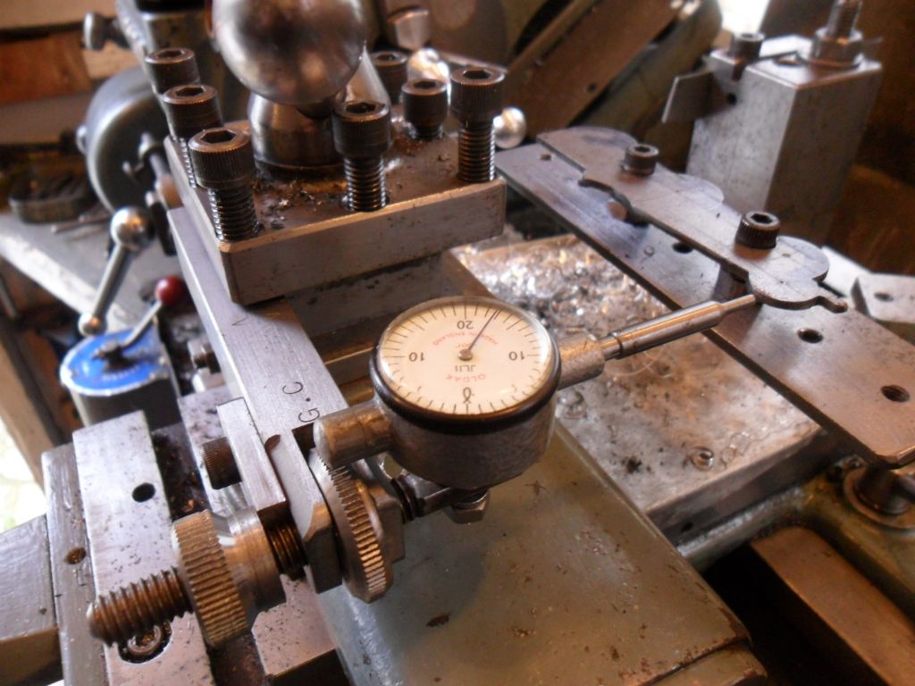
 587 forum posts 113 photos | I would say make a template like Mike says set up similar to my effort The template fits in to tailstock Nobby Edited By Nobby on 06/10/2017 23:22:51 |
| Hopper | 07/10/2017 02:16:02 |
 7881 forum posts 397 photos | Personally I'd turn the suggested tapers and blend it with a file, per Phil H1 above. But if I wanted to fiddle about and turn an exact 300mm radius, i would make up simple version of a ball turning tool. Piece of flat plate bolted to the cross slide, extending out the back of the lathe, with a pivot pin sticking up out of it, circa 300mm behind the centreline of the lathe spindle. Then a piece of long flat bar, circa 450mm long, with a hole drilled in one end to fit on the pivot pin in the bottom plate. Then attach a tool post, or any block with a slot to hold a lathe tool bit, positioned so the tool bit tip is exactly 300mm from the pivot pin centre. You then hold the end of the long flat bar as a handle (you could even fit a nice brass knob to it) and move the cross slide into position to centre the tool along the length of the to-be-curved section of the job. Gently sweep the end of the flat bar back and forth the required amount as the cross slide is fed in to put on the depth of cut. When the cuts at each end of the job meet in the middle, job's done. Once job is done, throw the whole device in the scrap box never to be used again. |
| Raglan Littlejohn | 07/10/2017 10:27:22 |
| 30 forum posts 21 photos | Nobby's idea is ideal for this job. I did a similar set up for a model loco smokebox door. Use slow power feed (sliding), and keep adjusting the cross slide to follow the template. you have to keep watching the dti, and try to keep the needle in the same place. Best to work from the middle of the template, as you have to wind the cross slide in to keep up. If you get behind with the cross slide you just stop cutting, and don't spoil the job. |
| Russell Eberhardt | 07/10/2017 11:26:40 |
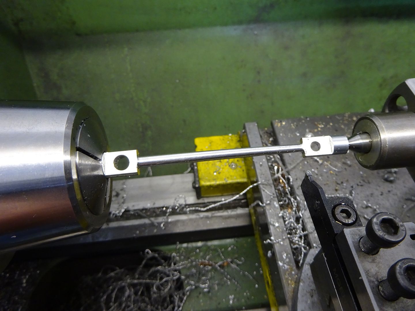
 2785 forum posts 87 photos | Many years ago I had to make some fish bellied pushrods for a 1930 sports car. They were very slender and tapered in a gentle curve at both ends to the ball end to reduce the reciprocating mass. The originals had been made by a knitting needle manufacturer! The method I used was to mount them near the centre in a collet and then support the end in a female centre which was offset to give the correct taper by bending the rod. That resulted in a nice curve in one pass. The ball ends were than case hardened and polished. The pushrods were about 1 ft long and 5 mm maximum diameter so flexed easily. It might not work on Dave's shorter rods but the method is worth remembering for longer rods. Russell |
| ega | 07/10/2017 11:41:12 |
| 2805 forum posts 219 photos | Russell Eberhardt: Your method sounds similar to the Tubal Cain method I mentioned earlier (my description of it was not very good). The fish-bellied push rods remind me of Bugatti's banana-shaped tappets. |
| Harold Hall 1 | 07/10/2017 13:02:32 |
| 418 forum posts 4 photos | Dave Have a look at my method shown on my website here **LINK** Harold |
| JasonB | 07/10/2017 13:14:21 |
25215 forum posts 3105 photos 1 articles | This one is done as a bender, I tend to use that more for rods that taper in one direction rather than two. Small live ctr in a boring head to get the offset.
The other thing that is not good in the OP's original drawing is the abrupt junction where rod meets flange and small end, just asking for a fracture, best to have a small internal radius where they meet. Edited By JasonB on 07/10/2017 13:16:13 |
| Andrew Johnston | 07/10/2017 15:41:44 |
 7061 forum posts 719 photos | Hydraulic copy unit and CNC milled pattern. If I was going to use handraulic methods I'd follow the approach set out by Phil H1. Which is exactly the method I used to form the crown on these pulley wheels:
So the radius isn't exactly 300mm? Who cares, it doesn't matter as long as it looks ok. Remember that the original was probably cast or forged so wasn't likely to be to drawing. If forged it was probably finished with files and emery paper anyway - kept the apprentices occupied. Andrew |
| Neil Wyatt | 07/10/2017 16:13:53 |
 19226 forum posts 749 photos 86 articles | As Jason has pointed out, if you copy the 300 radius you need to copy the sharp corners to be true to the design I would ask the original designer how HE did it! Anything other than blending some taper cuts seems OTT. I'm sure that's how I did this one...
|
| Russell Eberhardt | 07/10/2017 16:54:36 |
2785 forum posts 87 photos | Posted by ega on 07/10/2017 11:41:12:
The fish-bellied push rods remind me of Bugatti's banana-shaped tappets. The Talbot used an interesting rocker design as well:
|
| ega | 07/10/2017 17:28:08 |
| 2805 forum posts 219 photos | "The Talbot used an interesting rocker design as well:" Again, the aim seems to have been to reduce the reciprocating weight; I notice that the valves were waisted, too. Was the Talbot a Georges Roesch design? |
| Sam Longley 1 | 07/10/2017 17:30:05 |
| 965 forum posts 34 photos | Not that I know anything about these things but could one turn to near enough then mount a small grinder on a radiused arm & grind the final shape; or is that not a possible option to finish such things |


Please login to post a reply.
Magazine Locator
Want the latest issue of Model Engineer or Model Engineers' Workshop? Use our magazine locator links to find your nearest stockist!
Sign up to our Newsletter
Sign up to our newsletter and get a free digital issue.
You can unsubscribe at anytime. View our privacy policy at www.mortons.co.uk/privacy
Latest Forum Posts
- hemingway ball turner
04/07/2025 14:40:26 - *Oct 2023: FORUM MIGRATION TIMELINE*
05/10/2023 07:57:11 - Making ER11 collet chuck
05/10/2023 07:56:24 - What did you do today? 2023
05/10/2023 07:25:01 - Orrery
05/10/2023 06:00:41 - Wera hand-tools
05/10/2023 05:47:07 - New member
05/10/2023 04:40:11 - Problems with external pot on at1 vfd
05/10/2023 00:06:32 - Drain plug
04/10/2023 23:36:17 - digi phase converter for 10 machines.....
04/10/2023 23:13:48 - More Latest Posts...
- View All Topics
Support Our Partners


Shopping Partners
Subscription Offer

Latest "For Sale" Ads
- Reeves** - Rebuilt Royal Scot by Martin Evans
by John Broughton
£300.00 - BRITANNIA 5" GAUGE James Perrier
by Jon Seabright 1
£2,500.00 - Drill Grinder - for restoration
by Nigel Graham 2
£0.00 - WARCO WM18 MILLING MACHINE
by Alex Chudley
£1,200.00 - MYFORD SUPER 7 LATHE
by Alex Chudley
£2,000.00 - More "For Sale" Ads...
Latest "Wanted" Ads
- D1-3 backplate
by Michael Horley
Price Not Specified - fixed steady for a Colchester bantam mark1 800
by George Jervis
Price Not Specified - lbsc pansy
by JACK SIDEBOTHAM
Price Not Specified - Pratt Burnerd multifit chuck key.
by Tim Riome
Price Not Specified - BANDSAW BLADE WELDER
by HUGH
Price Not Specified - More "Wanted" Ads...
Get In Touch!
Do you want to contact the Model Engineer and Model Engineers' Workshop team?
You can contact us by phone, mail or email about the magazines including becoming a contributor, submitting reader's letters or making queries about articles. You can also get in touch about this website, advertising or other general issues.
Click THIS LINK for full contact details.
For subscription issues please see THIS LINK.
Digital Back Issues


Donate

 Register
 Log-in
Model Engineer Magazine
- Percival Marshall
- M.E. History
- LittleLEC
- M.E. Clock

ME Workshop
- An Adcock
- & Shipley
- Horizontal
- Mill

Subscribe Now
- Great savings
- Delivered to your door

Pre-order your copy!
- Delivered to your doorstep!
- Free UK delivery!
All Forum Topics > Workshop Techniques > How could I make this curved conrod?