Radius Tool
| Dave Cee | 26/01/2017 15:01:39 |
| 37 forum posts 20 photos |
Thanks
Edited By Dave Cee on 26/01/2017 15:02:06 |
| mechman48 | 26/01/2017 15:22:57 |
2947 forum posts 468 photos | Aren't you already creating a radius on the plate with the grinding wheel dia.? If I've got the wrong end of your question then you could use a boring head set up on the mill with the cutter set to the required radius, or even a fly cutter, also maybe a rota broach if you can borrow one of the correct diameter. |
| Jeff Dayman | 26/01/2017 15:26:57 |
| 2356 forum posts 47 photos | a) mark it out accurately and saw / grind/ file to the middle of the marked line. To mark out, pointed dividers set to radius with a vernier or digital caliper will be quite accurate. locate one point of dividers in a centre punch divot and scribe your line. To help see the line better, colour your plate with permanent marker or marking out fluid or engineers' blue prior to scribing. Also, when approaching the line in final filing, use 10X optical magnifier of some kind. b) send a DXF file for it to your local wire edm house, arrange money transfer, and wait for the postman Good luck JD |
| Dave Cee | 26/01/2017 15:27:19 |
| 37 forum posts 20 photos | Whoops sorry people. I meant the brake wheel on the end of the grinder. I don't have a mill as yet. Have a good lathe though. |
| John Haine | 26/01/2017 15:59:13 |
| 5563 forum posts 322 photos | You could try a form tool but sounds hard work. I have tackled this sort of job by creating a spreadsheet of feeds to form a semi-circular arc from the circle equation and used the handwheels and a lashed up DRO using a digital caliper for the longitudinal axis. That works fine - gives you a stepped approximation to the curve that you file to a smooth shape afterwards. I can give you some further information on doing this if you want. Nowadays I'd just give the problem to my CNC... Edited By John Haine on 26/01/2017 16:00:06 |
| pgk pgk | 26/01/2017 16:07:43 |
| 2661 forum posts 294 photos | If the radius matches a standard woodworking TCT router ball bearing bit you could do both sides then finish with files.. 10mins in here : |
| JasonB | 26/01/2017 16:21:23 |
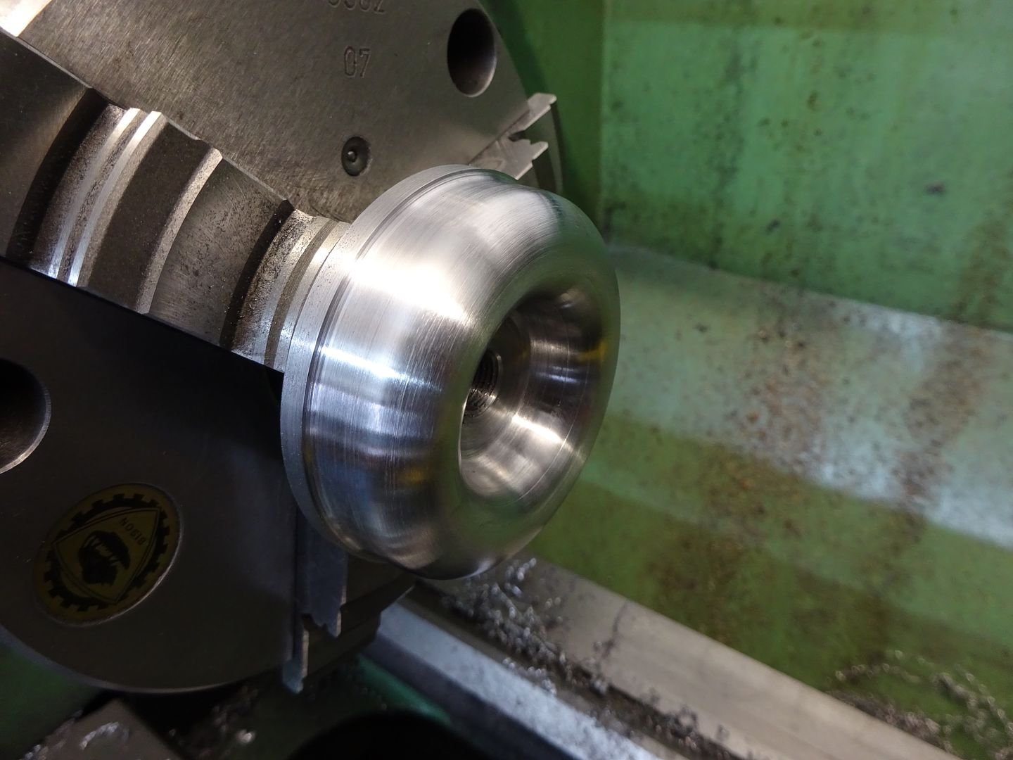
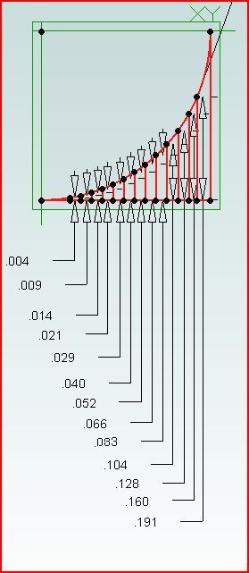
25215 forum posts 3105 photos 1 articles | As John H says work out a few co ordinates at regular intervals which will give you the basic shape then blend further by eye and finish with a file. This shape
use these co-ordinates
|
| Dave Cee | 26/01/2017 16:57:26 |
| 37 forum posts 20 photos | As a complete beginner I think I'm out of my depth on this one for now
Thanks for the replies guys will do some more research.
Dave. |
| pgk pgk | 26/01/2017 17:34:39 |
| 2661 forum posts 294 photos | It really isn't that difficult. I cut a profile that method on one of my first projects..(and I still don't know what I'm doing most of the time). No cad software so I drew it out on a scabby bit of graph paper and worked out the depth and length of cuts from that. Yeah, a lot easier with a DRO t keep track of the numbers but more than doable without. You can see i crossed each out as i got to it:
|
| Dennis D | 26/01/2017 17:58:36 |
| 84 forum posts 3 photos | Have a look at this **LINK** its for a ball end but looks like it could be modified to make the radius on the handle. You say you dont have a mill but if you have a drill press you might be able to drill a tapered hole or hold the taper bit in the chuck/collet on the lathe and clamp the workpiece to the toolpost. Edited By Dennis D on 26/01/2017 18:06:02 |
| Nick Hulme | 26/01/2017 19:25:12 |
| 750 forum posts 37 photos | Instead of calculating co-ordinates just use a fixed template (use your tailstock to mount it, it can be a drawing on card!) and a wire bent pointer from the tool-holder, - Nick |
| Tim Stevens | 26/01/2017 21:13:08 |
1779 forum posts 1 photos | One of the difficulties with questions like this is depends on working out what is meant. In this case, even when we are directed to the part referred to as 'this' we find a part with a radius all round the outside, and radii inside the outer edge and outside the inner one. So which radius needs to be created? This lack of precision can be baffling, especially to any beginners, non-english speakers, etc. My advice is to stand back from your question before you post it, and think how it might be interpreted. Add a few ounces* of clarity and you might just get several hundredweight* more sense in the responses. *And for beginners and non-English speakers these are old measures of weight - you might think 'spoonfuls and buckets'. Cheers, Tim |
| Dave Cee | 26/01/2017 21:36:43 |
| 37 forum posts 20 photos | This is part of an email that Gary from eccentric engineering kindly sent me. The brake wheel is just a large diameter aluminium disc cut from a piece of bar, I rounded the circumference on it with a radius form tool. The rest of making it etc I am comfortable with doing. I googled radius form tool but lots of different things came up. Cheers Dave. |
| Roderick Jenkins | 26/01/2017 21:44:15 |
2376 forum posts 800 photos | As the actual radius is largely cosmetic, I'd form the curves by hand with a graver and my GHT hand turning rest. Cheers, Rod |
| Hacksaw | 26/01/2017 21:47:32 |
| 474 forum posts 202 photos | I've never seen a brake wheel before . What is it for ? |
| Andrew Johnston | 26/01/2017 22:14:52 |
7061 forum posts 719 photos | It allows you to brake the grinding wheel, and break your wrist, all at the same time? Andrew |
| Dave Cee | 26/01/2017 22:21:29 |
| 37 forum posts 20 photos | Posted by Andrew Johnston on 26/01/2017 22:14:52:
It allows you to brake the grinding wheel, and break your wrist, all at the same time? Andrew Not if you put your hand underneath so it was trailing surely ? |
| Michael Gilligan | 26/01/2017 23:39:21 |
23121 forum posts 1360 photos | Dave, Although many of them are spoked [and therefore, potentially, even more risky], you might consider salvaging a hand-wheel from a sewing machine. MichaelG. |
| Hopper | 26/01/2017 23:59:11 |
7881 forum posts 397 photos | Easiest way for a beginner to get the job done with limited machinery might be to set the aluminium disc up in the lathe, probably mounted on a rough mandrel made from a bolt and nut, then by setting the top slide to progressively different angles, go around and machine a series of small flats on the OD approximating the shape you want. Start by setting the topslide to 45 degrees and make a large chamfer across half the OD surface, then move the top slide around to 30 degrees and make another smaller chamfer, then 15 degrees and repeat. Then move the topslide around to the the other side of the job and repeat teh process. Once you have a nice series of flats approximating the radius you want, you can finish the job off with a file while the job is spinning. It will help to make a rough radius gauge by drawing up and cutting out a piece of cardboard or plastic ice cream container etc etc just to make a reference to work to. |
| Tony Pratt 1 | 27/01/2017 07:28:04 |
| 2319 forum posts 13 photos | Going slightly off on a tangent, why would you want a brake wheel on a grinder, what's wrong with letting it run down when not under power? Tony |
Please login to post a reply.
Want the latest issue of Model Engineer or Model Engineers' Workshop? Use our magazine locator links to find your nearest stockist!
Sign up to our newsletter and get a free digital issue.
You can unsubscribe at anytime. View our privacy policy at www.mortons.co.uk/privacy
- hemingway ball turner
04/07/2025 14:40:26 - *Oct 2023: FORUM MIGRATION TIMELINE*
05/10/2023 07:57:11 - Making ER11 collet chuck
05/10/2023 07:56:24 - What did you do today? 2023
05/10/2023 07:25:01 - Orrery
05/10/2023 06:00:41 - Wera hand-tools
05/10/2023 05:47:07 - New member
05/10/2023 04:40:11 - Problems with external pot on at1 vfd
05/10/2023 00:06:32 - Drain plug
04/10/2023 23:36:17 - digi phase converter for 10 machines.....
04/10/2023 23:13:48 - More Latest Posts...
- View All Topics
- Reeves** - Rebuilt Royal Scot by Martin Evans
by John Broughton
£300.00 - BRITANNIA 5" GAUGE James Perrier
by Jon Seabright 1
£2,500.00 - Drill Grinder - for restoration
by Nigel Graham 2
£0.00 - WARCO WM18 MILLING MACHINE
by Alex Chudley
£1,200.00 - MYFORD SUPER 7 LATHE
by Alex Chudley
£2,000.00 - More "For Sale" Ads...
- D1-3 backplate
by Michael Horley
Price Not Specified - fixed steady for a Colchester bantam mark1 800
by George Jervis
Price Not Specified - lbsc pansy
by JACK SIDEBOTHAM
Price Not Specified - Pratt Burnerd multifit chuck key.
by Tim Riome
Price Not Specified - BANDSAW BLADE WELDER
by HUGH
Price Not Specified - More "Wanted" Ads...
Do you want to contact the Model Engineer and Model Engineers' Workshop team?
You can contact us by phone, mail or email about the magazines including becoming a contributor, submitting reader's letters or making queries about articles. You can also get in touch about this website, advertising or other general issues.
Click THIS LINK for full contact details.
For subscription issues please see THIS LINK.
Model Engineer Magazine
- Percival Marshall
- M.E. History
- LittleLEC
- M.E. Clock
ME Workshop
- An Adcock
- & Shipley
- Horizontal
- Mill
Subscribe Now
- Great savings
- Delivered to your door
Pre-order your copy!
- Delivered to your doorstep!
- Free UK delivery!


 Register
 Log-in


