Forum sponsored by:

Sourcing Worm and Wheel Gear Arrangement
Sourcing Worm and Wheel Gear Arrangement
| David Cambridge | 16/02/2016 09:11:06 |
| 252 forum posts 68 photos |
Thanks in advance, David
Edited By David Cambridge on 16/02/2016 09:11:43 |
| Les Jones 1 | 16/02/2016 09:22:55 |
| 2292 forum posts 159 photos | Hi David, Les.
|
| David Cambridge | 16/02/2016 09:34:56 |
| 252 forum posts 68 photos | Ah - yes. This image is on wikipedia for helical gears. The lower section is exactly what I'm after. Are they difficult to cut? (I'll have a look in my copy of Ivan Laws book this evening!). David
|
| David Cambridge | 16/02/2016 09:43:20 |
| 252 forum posts 68 photos | Now I now what I'm looking for http://hpcgears.com looks like a good option! |
| John Stevenson | 16/02/2016 09:48:32 |
 5068 forum posts 3 photos | Correct they are called skew gears which are just helicals with the same hand.
Normally helicals operating in the same plane need to be opposite hand but if mounted in the a 90 degree plane they need to be same hand.
Normal plane.
Opposite plane.
|
| Roderick Jenkins | 16/02/2016 10:25:10 |
 2376 forum posts 800 photos | David, Sadly, Ivan law doesn't go into helical gears in his book. I made a pair of gears for my Wyvern engine which uses a similar arrangement on a 1/2" crankshaft and a 1/4" sideshaft. I think Hemingway do the gears. Diane has an article on how I made mine which may be suitable for publication. We had quite a discussion on an earlier thread HTH, Rod |
| John P | 16/02/2016 11:01:12 |
| 451 forum posts 268 photos | Hi David There was in the Model engineer some time ago an interesting Seen in album " gears " 3 photos 2 are from article MEW 193 John |
| Ajohnw | 16/02/2016 12:06:12 |
| 3631 forum posts 160 photos | There is a person in the Ukraine selling various hobs pretty cheaply on ebay uk and usa. He has 0.8mod, other sizes and some of the usual gear cutters as well. Russian work at it's finest going on some I bought. John - |
| Tim Stevens | 17/02/2016 21:44:27 |
 1779 forum posts 1 photos | One aspect of skew gears to remember - especially on drives like camshafts where the load is high and variable - is to ensure copious lubrication. Another is to ensure that end float of either gear is eliminated (so far as poss). On my 1928 car with a skew gear to drive the magneto (a light load) the gears are trapped between thrust bearings, and the pressure relief from the oil pump blows all the 'spare' oil onto the gear just ahead of engagement. Cheers, Tim |
| Ian S C | 18/02/2016 10:46:07 |
 7468 forum posts 230 photos | I agree with Tim, under much of a load the wear is quite high, its best if the gears are of different materials, ie. steel for one, and bronze for the other. Reason is that the action is a sliding one, and unless they are cast iron, two like metals can tend to pick up on each other, although the brass Meccano ones seem to do all right. I suppose you could liken a skew gear to a multi start worm. Ian S C |
| David Cambridge | 18/02/2016 13:02:46 |
| 252 forum posts 68 photos | I think there is still something fundamental going on that I don’t understand. If I want a 2:1 ratio between the crank and cam shaft, and I look at helical gears on hpcgears.com the diameter of the large gear (I’d use this for the cam shaft) is twice that of the small gear(Id use this for the crank shaft). Since PD = N/DP that seems fair enough. But, when I look at the photos like the image of a Find Hansen engine at the top of this thread, the two gears look either the same size or the opposite way round to what I was expecting ? David |
| David Cambridge | 18/02/2016 13:13:47 |
| 252 forum posts 68 photos | |
| Roderick Jenkins | 18/02/2016 13:19:23 |
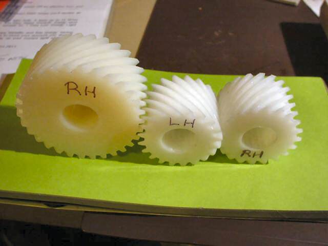
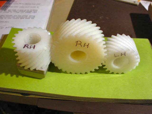
2376 forum posts 800 photos | David, It depends on the helix angle. For helical gears, if you want a right angle drive then the helix angles just have to add up to 90 degrees. The pitch diameter of a helical gear is given by N divided by (DP x Cos(A)) where N is the number of teeth, DP is the Diametrical Pitch and A is the helix angle. For 45 degree helix angles Cos (A) =1 so the relative diameters depend soley on the number of teeth - 36 teeth will be twice the diameter of an 18 tooth. If you choose 26.6 degrees and 63.4 degrees for the 2 helix angles then you end up with 2:1 gears that have the same OD - which is what the Wyvern uses:
HTH, Rod Edited By Roderick Jenkins on 18/02/2016 13:20:47 To correct the error MichaelG pointed out below Edited By Roderick Jenkins on 18/02/2016 13:33:04 |
| Michael Gilligan | 18/02/2016 13:26:23 |
 23121 forum posts 1360 photos | Posted by Roderick Jenkins on 18/02/2016 13:19:23: For helical gears, if you want a right angle drive then the helix angles just have to add up to 90 degrees. If you choose 36.6 degrees and 63.4 degrees for the 2 helix angles then you end up with 2:1 gears that have the same OD - which is what the Wyvern uses: . Rod, Forgive me if I am being very stupid today, but: 36.6 + 63.4 = 100 Does it not ? MichaelG. |
| JasonB | 18/02/2016 13:27:23 |
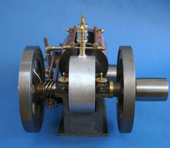
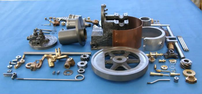
 25215 forum posts 3105 photos 1 articles | You can see the angle on this Domestic that I made, the shallow angle on the crank gear lets it be larger than the cam gear where you would normally find the opposite with spur gears. This allows the larger dia crank to pass through without such a thin wall as in Rod's photo
Better shot where you can see the helix of both gears
Edited By JasonB on 18/02/2016 13:28:57 Edited By JasonB on 18/02/2016 13:30:56 |
| Roderick Jenkins | 18/02/2016 13:31:19 |
2376 forum posts 800 photos | Posted by Michael Gilligan on 18/02/2016 13:26:23:
Posted by Roderick Jenkins on 18/02/2016 13:19:23: For helical gears, if you want a right angle drive then the helix angles just have to add up to 90 degrees. If you choose 36.6 degrees and 63.4 degrees for the 2 helix angles then you end up with 2:1 gears that have the same OD - which is what the Wyvern uses: . Rod, Forgive me if I am being very stupid today, but: 36.6 + 63.4 = 100 Does it not ? MichaelG. Not as stupid as me! Sorry, typo - should be 26.6 Rod
Rod |
| David Cambridge | 18/02/2016 13:37:25 |
| 252 forum posts 68 photos | Thanks everyone. The missing part of my understanding was the cos(A) in the formula David |
| Martin Connelly | 18/02/2016 13:55:04 |
 2549 forum posts 235 photos | If we are picking holes in this then cos(45) does not equal 1, Tan(45) equals 1 and cos(45) is 0.707 (square root of 2). Martin |
| Martin Connelly | 18/02/2016 14:31:10 |
2549 forum posts 235 photos | Further to this 2:1 ratio in similar sized diameters for skew gears: The angles in the example above are found from the inverse tan of 0.5 and 2 (half the speed one way and double the speed the other). Tan(63.435)=2 Tan(26.565)=0.5 The angles have been rounded to 3 significant decimals. If they are rounded to 1 decimal you get the angles stated earlier. Hope this helps anyone considering other possible ratios. Martin
|
| Roderick Jenkins | 18/02/2016 14:57:56 |
2376 forum posts 800 photos | Posted by Martin Connelly on 18/02/2016 13:55:04:
If we are picking holes in this then cos(45) does not equal 1, Tan(45) equals 1 and cos(45) is 0.707 (square root of 2). Martin Pick holes we must - got to get it right. The point I should have been trying to make was that with both gears at 45 degrees you use the same divisor, so that the relative diameters stay in proportion to the teeth number. Sorry again - must try not to rush things. Rod |


Please login to post a reply.
Magazine Locator
Want the latest issue of Model Engineer or Model Engineers' Workshop? Use our magazine locator links to find your nearest stockist!
Sign up to our Newsletter
Sign up to our newsletter and get a free digital issue.
You can unsubscribe at anytime. View our privacy policy at www.mortons.co.uk/privacy
Latest Forum Posts
- *Oct 2023: FORUM MIGRATION TIMELINE*
05/10/2023 07:57:11 - Making ER11 collet chuck
05/10/2023 07:56:24 - What did you do today? 2023
05/10/2023 07:25:01 - Orrery
05/10/2023 06:00:41 - Wera hand-tools
05/10/2023 05:47:07 - New member
05/10/2023 04:40:11 - Problems with external pot on at1 vfd
05/10/2023 00:06:32 - Drain plug
04/10/2023 23:36:17 - digi phase converter for 10 machines.....
04/10/2023 23:13:48 - Winter Storage Of Locomotives
04/10/2023 21:02:11 - More Latest Posts...
- View All Topics
Support Our Partners


Shopping Partners
Subscription Offer

Latest "For Sale" Ads
- Reeves** - Rebuilt Royal Scot by Martin Evans
by John Broughton
£300.00 - BRITANNIA 5" GAUGE James Perrier
by Jon Seabright 1
£2,500.00 - Drill Grinder - for restoration
by Nigel Graham 2
£0.00 - WARCO WM18 MILLING MACHINE
by Alex Chudley
£1,200.00 - MYFORD SUPER 7 LATHE
by Alex Chudley
£2,000.00 - More "For Sale" Ads...
Latest "Wanted" Ads
- D1-3 backplate
by Michael Horley
Price Not Specified - fixed steady for a Colchester bantam mark1 800
by George Jervis
Price Not Specified - lbsc pansy
by JACK SIDEBOTHAM
Price Not Specified - Pratt Burnerd multifit chuck key.
by Tim Riome
Price Not Specified - BANDSAW BLADE WELDER
by HUGH
Price Not Specified - More "Wanted" Ads...
Get In Touch!
Do you want to contact the Model Engineer and Model Engineers' Workshop team?
You can contact us by phone, mail or email about the magazines including becoming a contributor, submitting reader's letters or making queries about articles. You can also get in touch about this website, advertising or other general issues.
Click THIS LINK for full contact details.
For subscription issues please see THIS LINK.
Digital Back Issues


Donate

 Register
 Log-in
Model Engineer Magazine
- Percival Marshall
- M.E. History
- LittleLEC
- M.E. Clock

ME Workshop
- An Adcock
- & Shipley
- Horizontal
- Mill

Subscribe Now
- Great savings
- Delivered to your door

Pre-order your copy!
- Delivered to your doorstep!
- Free UK delivery!
All Forum Topics > General Questions > Sourcing Worm and Wheel Gear Arrangement