Forum sponsored by:

4 Jaw Work
An accuracy exercise
| Jack Foreman 1 | 02/10/2014 15:40:48 |
 99 forum posts 17 photos |
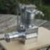
I'm not sure if this is the correct Topic Section for this. If not, can a Mod move it appropriately please? Started from a small aluminium billet. 4 spigots, each in line on their respective centre-lines. Probably not the best turning in the world, and certainly not the best photography, but I'm pleased with the result.
Edited By Jack Foreman 1 on 02/10/2014 15:47:24 Edited By Jack Foreman 1 on 02/10/2014 15:47:53 Edited By Jack Foreman 1 on 02/10/2014 15:48:32 |
| Neil Wyatt | 02/10/2014 16:00:13 |
 19226 forum posts 749 photos 86 articles | Nicely done, looks like brass. It looks like an injector body, perhaps you should try making one as your next exercise in precision work? Neil |
| Jack Foreman 1 | 02/10/2014 19:30:16 |
99 forum posts 17 photos | The brass effect is a combination of the lighting in the workshop and converting Raw into jpg on Photoshop Neil. What is an injector body? This afternoon I set up a 1-1/2"bar in the 4 jaw chuck using a dial gauge to true it up. That's a first too. |
| Ian P | 02/10/2014 20:51:13 |
 2747 forum posts 123 photos | Jack I am sure that is not an easy part to make and now I'm wondering how you did it! If the block was accurately rectangular I could imagine marking it out on a surface plate, then you would have to centrepunch each centre and pick those up in the 4 jaw. That would rely on your centrepunching being better than 0.0005" so good eyesight and steady hands are needed. Without any pre marking out I could imagine setting up the block in the 4 jaw using a DTI on the corners, that would work for the concentric bosses but only if the block corners were identical in terms of their precise corner geometry (no, or identical radii). That technique would be much more difficult with the offset bosses. All in all a neat job, but how? Ian P
|
| Jack Foreman 1 | 02/10/2014 21:14:48 |
99 forum posts 17 photos | Ian, the blank was simply an off-cut from a standard aluminium rectangular 35mm 20mm section x 58mm long. Edited By Jack Foreman 1 on 02/10/2014 21:17:32 |
| Neil Wyatt | 02/10/2014 21:16:03 |
19226 forum posts 749 photos 86 articles | A cunning device for pumping water into a boiler using its own steam pressure with remarkable efficiency.
The black bit is the body. See what I mean? Neil |
| Jack Foreman 1 | 02/10/2014 21:27:59 |
99 forum posts 17 photos | My word Neil - that looks a sophisticated piece of kit. And presumably it has interconnected passages between each of the connection points too. I do see what you mean about the similarity in profile. And presumably the brass fittings are also made and threaded on the lathe too? Next though is a double ended die holder with an arbor and a 3MT shank, for the tailstock. |
| Ian P | 02/10/2014 21:41:37 |
2747 forum posts 123 photos | Jack In my experience standard ali extrusion rarely has sides that are very flat and I think there is probably more than half a thou allowance regarding the nominal size. For your part the exact dimensions are not important but centering the bosses to your tolerance is no easy feat, so I'm impressed. Ian P
|
| wheeltapper | 02/10/2014 22:47:00 |
 424 forum posts 98 photos | Posted by Jack Foreman 1 on 02/10/2014 21:27:59:
"snip". And presumably the brass fittings are also made and threaded on the lathe too? Snip
I think if you saw the inside of one you may change your mind.
Roy. |
| Jack Foreman 1 | 02/10/2014 22:51:37 |
99 forum posts 17 photos | Thanks for the tip Roy. Perhaps I'll put that one aside 'for-the-future' |
| Gary Wooding | 03/10/2014 08:34:11 |
| 1074 forum posts 290 photos | This is a fairly typical injector. |
| Ian S C | 03/10/2014 11:18:59 |
 7468 forum posts 230 photos | Jack, don't worry about the stutter, a good many of us do it. |
| Jack Foreman 1 | 03/10/2014 12:57:08 |
99 forum posts 17 photos | Posted by Gary Wooding on 03/10/2014 08:34:11:
This is a fairly typical injector. My word Gary, that is considerably more complex than I imagined.
|
| Jack Foreman 1 | 03/10/2014 12:57:29 |
99 forum posts 17 photos | Posted by Ian S C on 03/10/2014 11:18:59:
Jack, don't worry about the stutter, a good many of us do it. Thanks Ian - that's reassuring
|
| Gary Wooding | 03/10/2014 16:07:23 |
| 1074 forum posts 290 photos | Posted by Jack Foreman 1 on 03/10/2014 12:57:08:
My word Gary, that is considerably more complex than I imagined.
At first I thought that the body must be a casting - then I saw that it can be machined on the lathe, following the correct procedure. The inserts look fiddly and time consuming.
It seems impossible that the steam from the boiler can push water into the same boiler, but it does. The basic mechanism is that the jet of steam converts the cold water into tiny droplets and accelerates them so that their inertia is sufficient to overcome the pressure inside the boiler. In practise, the inlet water must be cold, they don't work very well, if at all, if the water is warm. The machining requires very high precision, especially for ones intended for small 3.5" or 5" locos. Many people just give up before they get one that works. The larger ones, whilst still critical, are a little easier to make. |
| Andrew Johnston | 03/10/2014 16:44:29 |
 7061 forum posts 719 photos | Posted by Gary Wooding on 03/10/2014 16:07:23:
The basic mechanism is that the jet of steam converts the cold water into tiny droplets and accelerates them so that their inertia is sufficient to overcome the pressure inside the boiler. In practise, the inlet water must be cold, they don't work very well, if at all, if the water is warm. I'm afraid I don't quite follow that? If a fixed mass of input steam has a certain amount of potential energy associated with it's pressure how can it accelerate a greater mass of water to a higher pressure? Where does the extra energy come from? Andrew |
| Neil Wyatt | 03/10/2014 17:03:12 |
19226 forum posts 749 photos 86 articles | It's counterintuitive, but this is how I understand the mechanism in simplified terms: The steam accelerates as it goes through the first cone, the extra energy has to come from somewhere so it gets colder but it's kinetic energy is proportionately increased. As the stream passes through the next cone it combines with the water and accelerates it through the next cone, energy for this is partly from the latent heat released when the steam condenses. Eventually the water and steam re-enter the boiler having only wasted a fairly small amount of energy as heat radiated from pipework and the injector. A work of thermodynamic genius! Neil |
| jason udall | 03/10/2014 17:23:36 |
| 2032 forum posts 41 photos | ...a work of thermodynamic genius. ... And dangerously close to witchcraft |
| Hacksaw | 03/10/2014 17:26:28 |
| 474 forum posts 202 photos | They work by black magic.. But work they do ! I have an O level " A" pass in Physics , and i'm buggered if i can get my head around how they work still My Dads really, really brainy...can even do a Rubik cube !! But, he can't see how a jet engine can work ! And lets face it, they're really simple !! Edited By Hacksaw on 03/10/2014 17:27:13 Edited By Hacksaw on 03/10/2014 17:29:02 |
| Andrew Johnston | 03/10/2014 17:31:52 |
7061 forum posts 719 photos | I thought that the steam cone converted the potential energy due to the pressure to kinetic energy, no extra energy was added? At the outlet of the steam cone the steam pressure is below atmospheric so water is sucked into the space. This is then accelerated by the steam jet, which also slows down; conservation of momentum? As Neil correctly says the feed water also condenses the steam, releasing the enthalpy of evaporation, which heats the water jet. This is where the extra energy comes from. The water jet is then slowed, converting the kinetic energy to pressure energy. I think that is why warm feed water isn't good, as it doesn't condense the stream properly, so the extra energy needed is not available. Being an awkward so and so, when the time comes, I am planning to have a go at designing and building my own injectors for my traction engines. Regards, Andrew |


Please login to post a reply.
Magazine Locator
Want the latest issue of Model Engineer or Model Engineers' Workshop? Use our magazine locator links to find your nearest stockist!
Sign up to our Newsletter
Sign up to our newsletter and get a free digital issue.
You can unsubscribe at anytime. View our privacy policy at www.mortons.co.uk/privacy
Latest Forum Posts
- *Oct 2023: FORUM MIGRATION TIMELINE*
05/10/2023 07:57:11 - Making ER11 collet chuck
05/10/2023 07:56:24 - What did you do today? 2023
05/10/2023 07:25:01 - Orrery
05/10/2023 06:00:41 - Wera hand-tools
05/10/2023 05:47:07 - New member
05/10/2023 04:40:11 - Problems with external pot on at1 vfd
05/10/2023 00:06:32 - Drain plug
04/10/2023 23:36:17 - digi phase converter for 10 machines.....
04/10/2023 23:13:48 - Winter Storage Of Locomotives
04/10/2023 21:02:11 - More Latest Posts...
- View All Topics
Support Our Partners


Shopping Partners
Subscription Offer

Latest "For Sale" Ads
- Reeves** - Rebuilt Royal Scot by Martin Evans
by John Broughton
£300.00 - BRITANNIA 5" GAUGE James Perrier
by Jon Seabright 1
£2,500.00 - Drill Grinder - for restoration
by Nigel Graham 2
£0.00 - WARCO WM18 MILLING MACHINE
by Alex Chudley
£1,200.00 - MYFORD SUPER 7 LATHE
by Alex Chudley
£2,000.00 - More "For Sale" Ads...
Latest "Wanted" Ads
- D1-3 backplate
by Michael Horley
Price Not Specified - fixed steady for a Colchester bantam mark1 800
by George Jervis
Price Not Specified - lbsc pansy
by JACK SIDEBOTHAM
Price Not Specified - Pratt Burnerd multifit chuck key.
by Tim Riome
Price Not Specified - BANDSAW BLADE WELDER
by HUGH
Price Not Specified - More "Wanted" Ads...
Get In Touch!
Do you want to contact the Model Engineer and Model Engineers' Workshop team?
You can contact us by phone, mail or email about the magazines including becoming a contributor, submitting reader's letters or making queries about articles. You can also get in touch about this website, advertising or other general issues.
Click THIS LINK for full contact details.
For subscription issues please see THIS LINK.
Digital Back Issues


Donate

 Register
 Log-in
Model Engineer Magazine
- Percival Marshall
- M.E. History
- LittleLEC
- M.E. Clock

ME Workshop
- An Adcock
- & Shipley
- Horizontal
- Mill

Subscribe Now
- Great savings
- Delivered to your door

Pre-order your copy!
- Delivered to your doorstep!
- Free UK delivery!
All Forum Topics > Workshop Techniques > 4 Jaw Work