Forum sponsored by:

WARCO WM-250 lathe family and WM16 mill - 001
........advice and support for owners.
| Rik Shaw | 01/07/2013 16:54:09 |
 1494 forum posts 403 photos |
George - Grizzly manual gives instructions for "running in" a new lathe (which I have done). This is followed by their reccomendation to change the oil - which I have not done. But I will once I have figured out where the drain plugs are. Given the amount of foundry sand I have found everywhere I think their advice is sound. ------ Rik PS thanks for the SAE 20 tip, I was wondering about ISO 60 which incidentally would not apply to me as ISO 66 |
| mechman48 | 02/07/2013 10:36:10 |
 2947 forum posts 468 photos | Rik /all Have att. info for ref: Viscosity Classifications - Tribology-ABC . Look at table # 5 it gives the equivalent for ISO 46 - 68 = SAE 20.. which covers what we need hence why I put SAE 15 - 40 in for topping up, the equivalent in the gear oil range is shown as 75 - 80W so you could replace your oil with this on change out, Halfords (no connection) or similar shop generally have multi range gearbox oil,could be marked up as Hypoid / GTX 70 - 90W.. ? I'll probably go this route when I change mine. Drain plugs: Warco manual.. Lathe Gearbox Assembly page .. part # 11. Lathe Apron Assembly page .. part # 27 looks to be the drain plug although this is described as 'screw' (usual excellent chinglish translation) check on your machine! I'v looked up the Grizzly equivalent machine & as near as matters is the G0752.. pdf parts list page 84 .. gearbox..part # 814.. drain plug. It doesn't show where the apron drain plug is but logical deduction is that it would be underneath near the sight glass or low down on one of the ends of the apron casting. PS, have just checked on mine & there is a SH screw underneath the autofeed (half nut ) lever which may well be the drain plug but looking at the Warco manual this is not identified other than showing as an unidentfied screw,with what looks like a ball bearing on top, nestled in between part #'s 28..'screw' & # 29 'Label'.. ? whatever the case it will be awkward to remove & refit. the alternative would be to remove the hex head sight glass(on mine) drain off from there & refill from the SH screw on the left side of the apron (3/4 way up casting) until clean oil comes out of the sight glass location,refit the glass & top up to 3/4 level. I can't see part # 27 'screw' unless it is flush & has been painted over when they have sprayed the casting (any other owners noted / resolved this point)..? Cheers George
Edited By mechman48 on 02/07/2013 11:01:54 Edited By mechman48 on 02/07/2013 11:04:55 |
| Thor 🇳🇴 | 02/07/2013 18:21:06 |
 1766 forum posts 46 photos | Hi George, thanks for the link to the Viscosity Classification. On my new lathe the drain plug is situated on the underside of the apron, at the left end closest to the headstock. I have a photo showing the apron.
Thor Edited By Thor on 02/07/2013 18:21:39 Edited By Thor on 02/07/2013 18:22:25 |
| john kennedy 1 | 11/07/2013 12:40:34 |
 214 forum posts 24 photos | Hi everyone, I've had my WM250 lathe for about 3 1/2 years and up to now its served me well. I've come to stage where I need to cut a 12mm thread with a 1.75mm pitch. I've got to admit that I'm baffled by the thread table on the gear cover and also the manual. (which conflict on the gear sizes given) I can't work out what H & L mean (headstock & leadscrew perhaps?) Also it only shows 4 gears in the train, Z1 being represented by H, unlike 5 gears in the slow feed train. Also do the dotted lines in the manual or the small marks on the gear cover plate represent gears in mesh or gears on the same quadrant bolt??? Would someone please explain how I can arrive at the correct train. Thanks, John. |
| SteveW | 11/07/2013 13:09:40 |
 140 forum posts 11 photos | I'd be happier to calculate myself. Does anyone know what the leadscrew pitch (metric) is? And how many teeth on the headstock/spindle gear? I distrust tables (having been caught once) but perhaps that's just me! SteveW |
| JasonB | 11/07/2013 13:25:23 |
 25215 forum posts 3105 photos 1 articles | H means there is no gear, use a spacer either from when you remove the feed ratios or in the box with the change gears L is the leadscrew gear The vertical dash between mumbers show that the gear above meshes with the one below Numbers side by side are on the same bolt eg Z1 & Z2 are on one stud, Z3 & Z4 on another |
| JasonB | 11/07/2013 13:48:06 |
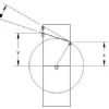
25215 forum posts 3105 photos 1 articles | This may make it a bit clearer, gears based on the WM280 which may differ from the 250. to give 1.75mm pitch with metric leadscrew Front selector in "A"
Click to make it bigger. Do check it first as I have found errors in the 280 chart relating to which position the front dial should be in but have only corrected teh imperial threads as I have a 8tpi leadscrew Edited By JasonB on 11/07/2013 13:50:57 |
| john kennedy 1 | 11/07/2013 14:15:07 |
214 forum posts 24 photos | Thanks Jason for taking the trouble to do a diagram.I can get my head round it now and try the gears shown in both tables. I'll do a test piece first and check with a gauge. By the way mine is a metric lathe with a 3mm leadscrew. Steve, is there a formula to check I'll eventually have the correct gears? ... John |
| mechman48 | 12/07/2013 07:40:47 |
2947 forum posts 468 photos | HI All, Help.... My WM16 vertical digital (Z axis) scale has just gone haywire; whatever amount I put on e.g..020" or .5mm doesn't register correctly comes up with something stupid like 6.250" , even 150.25mm. I have put new battery in, checked all fastenings are tight, zero'd everything but it's just throwing readings up of all description & reading flickers between stupid numbers even when I have managed to set a d.o.c. ...sounds like the electronics have given up the ghost. I think it's still just in warranty, will check paperwork & contact Warco for replacement if so, but if not (or Warco's want to play silly buggers?) any owners have a solution ? George |
| JasonB | 12/07/2013 08:16:28 |
25215 forum posts 3105 photos 1 articles | John, this is the formula based on my Imperial 280 but assuming its got a metric leadscrew, the head and gearbox should be the same on both its just the leadscrew that would be different. We know the leadscrew will move the carrage 3mm per revolution of the chuck but we want it to only move by 1.75mm per rev so 1.75/3.00 = 0.583333 Now to get the same number with the gears Basically divide the driver by the driven so the 40T spindle drives the 50T, 50T drives the 80T, 70T drives the 60T, this gives us the fractions 40/50, 50/80 & 70/60 noe expressed as decimals 0.8, 0.625 & 1.16666. The gearbox ratios are A=1:1, B=2:1 & C=1:2 which give the decimals 1, 2 & 0.5. You now multipy these decimals so 0.8 x 0.625 x 1.16666 x 1 = 0.583333 If the two numbers are the same you have got it right. In our case they both come out at 0.583333
Edited By JasonB on 12/07/2013 08:16:54 |
| Rik Shaw | 12/07/2013 08:54:27 |
1494 forum posts 403 photos | Keep us informed about your duff dro on your mill George. On the subject of DRO,s, as far as I can make out there are two types of DRO available from WARCO (and others) for these machines. One type seems to be a simple strip with an integral readout and the other appears to be some sort of expensive glass scale used in conjunction with a separate larger display. If the above is correct, how are both types of scale affixed to the machine? Rik |
| SteveW | 12/07/2013 09:15:26 |
140 forum posts 11 photos | John, I think Jason has done well to explain what has to be done. It seems much more complicated in metric - again I think that's just me... I think of it as 'how many times slower do you want the leadscrew to go compared to its existing pitch/tpi'. If the leadscrew was the same speed as the spindle you would cut the same pitch thread as the leadscrew. SteveW |
| JasonB | 12/07/2013 10:16:34 |
25215 forum posts 3105 photos 1 articles | Rik its just a case of drilling and tapping some holes on the machine where ever suits. The glass scales are far less temprimental than the calliper type scales plus you get all the functions of the display head.
J |
| john kennedy 1 | 12/07/2013 10:44:03 |
214 forum posts 24 photos | Thanks again Jason,you make it look so easy. I got it set up last night 30-80 70-60 but didn't have time to do the test piece. Will update. John |
| Ady1 | 12/07/2013 10:47:36 |
 6137 forum posts 893 photos | its just a case of drilling and tapping some holes on the machine where ever suits. If anyone is wondering about this because they haven't done it before, cast iron drills and taps extremely easily If your hss drill struggles for whatever reason those small carbide tipped masonry drills sail through cast iron and can be used to make a pilot hole |
| Andrew Johnston | 12/07/2013 10:57:49 |
 7061 forum posts 719 photos |
Posted by SteveW on 12/07/2013 09:15:26:
It seems much more complicated in metric - again I think that's just me... No, it's not just you, the maths is more complicated. If you look at a thread dial indicator for an imperial lathe there's normally just a single 'gear' to engage with the leadscrew. On a metric lathe the thread dial indicator will have a stack of 'gears' which have to be selected depending on the thread pitch. Regards, Andrew |
| mechman48 | 12/07/2013 10:59:02 |
2947 forum posts 468 photos | Rik My DRO's are magnetic strips with remote linked readouts via cable, purchased from another supplier but very similar to Warco's. They come supplied with fixing brackets, the read head bracket can be modified to suit the machine but I made a new bracket to suit, not difficult to fit. George ps. just remember to keep the bar level Edited By mechman48 on 12/07/2013 11:21:14 |
| john kennedy 1 | 13/07/2013 15:48:15 |
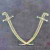
214 forum posts 24 photos | Just an update, due to your help I managed to cut the thread on my wm250. The nut fits very well with no shake. Set the topslide over to the 60 deg mark and fed that in 1.2mm. Its for the retaining nut on a new leadscrew I'm fitting to my Harrison milling machine. You'll notice I'm using a Diamond tool holder that comes with a jig to grind the tool to 6o deg. Thought it was a bit of a gimmick at first but if you set the jig screw at the correct angle (trial and error) it comes out great. Thanks again for your help. John
|
| Rik Shaw | 14/07/2013 17:33:16 |
1494 forum posts 403 photos | I ordered a new collet chuck with my lathe and would have used it this afternoon but discovered that the backplate that came with it needs to have a locating boss machined on it to take the chuck. Although the chuck has three tapped holes I was contemplating opening them up to clearance and drill and tap the backplate but then realised that the backplate has been hardened - so drilling is probably out. Is it normal for WARCO to expect the customer to do the machining? Maybe the job is a better one done on the customers own machine - I don't know. The backplate shown is "as delivered". Rik
|
| JasonB | 14/07/2013 17:37:57 |
25215 forum posts 3105 photos 1 articles | Backplates should always be turned in-situ to get them concentric to your spindle. Also make sure you put a mark on the backplate so it always goes back on the same way in much the same was as your 3-jaw is marked The three tapped holes in the backplate are probably on the correct PCD for the studs that go through the mounting flange, you will need to drill for suitable fixings to attach the chuck to the backplate. Best to counter bore from the rear of the backplate and screw into the chuck, that way the front is nice and clear with nothing to catch your hand or tools on. J Edited By JasonB on 14/07/2013 17:42:55 |


Please login to post a reply.
Magazine Locator
Want the latest issue of Model Engineer or Model Engineers' Workshop? Use our magazine locator links to find your nearest stockist!
Sign up to our Newsletter
Sign up to our newsletter and get a free digital issue.
You can unsubscribe at anytime. View our privacy policy at www.mortons.co.uk/privacy
Latest Forum Posts
- *Oct 2023: FORUM MIGRATION TIMELINE*
05/10/2023 07:57:11 - Making ER11 collet chuck
05/10/2023 07:56:24 - What did you do today? 2023
05/10/2023 07:25:01 - Orrery
05/10/2023 06:00:41 - Wera hand-tools
05/10/2023 05:47:07 - New member
05/10/2023 04:40:11 - Problems with external pot on at1 vfd
05/10/2023 00:06:32 - Drain plug
04/10/2023 23:36:17 - digi phase converter for 10 machines.....
04/10/2023 23:13:48 - Winter Storage Of Locomotives
04/10/2023 21:02:11 - More Latest Posts...
- View All Topics
Support Our Partners


Shopping Partners
Subscription Offer

Latest "For Sale" Ads
- Reeves** - Rebuilt Royal Scot by Martin Evans
by John Broughton
£300.00 - BRITANNIA 5" GAUGE James Perrier
by Jon Seabright 1
£2,500.00 - Drill Grinder - for restoration
by Nigel Graham 2
£0.00 - WARCO WM18 MILLING MACHINE
by Alex Chudley
£1,200.00 - MYFORD SUPER 7 LATHE
by Alex Chudley
£2,000.00 - More "For Sale" Ads...
Latest "Wanted" Ads
- D1-3 backplate
by Michael Horley
Price Not Specified - fixed steady for a Colchester bantam mark1 800
by George Jervis
Price Not Specified - lbsc pansy
by JACK SIDEBOTHAM
Price Not Specified - Pratt Burnerd multifit chuck key.
by Tim Riome
Price Not Specified - BANDSAW BLADE WELDER
by HUGH
Price Not Specified - More "Wanted" Ads...
Get In Touch!
Do you want to contact the Model Engineer and Model Engineers' Workshop team?
You can contact us by phone, mail or email about the magazines including becoming a contributor, submitting reader's letters or making queries about articles. You can also get in touch about this website, advertising or other general issues.
Click THIS LINK for full contact details.
For subscription issues please see THIS LINK.
Digital Back Issues


Donate

 Register
 Log-in
Model Engineer Magazine
- Percival Marshall
- M.E. History
- LittleLEC
- M.E. Clock

ME Workshop
- An Adcock
- & Shipley
- Horizontal
- Mill

Subscribe Now
- Great savings
- Delivered to your door

Pre-order your copy!
- Delivered to your doorstep!
- Free UK delivery!
All Forum Topics > Workshop Tools and Tooling > WARCO WM-250 lathe family and WM16 mill - 001