Forum sponsored by:

The Workshop Progress thread 2018
| Jim Nic | 12/09/2018 21:02:49 |
 406 forum posts 235 photos | By eck Jason that's a flywheel and a half and no mistake. Once you get that spinning it'll carry on for ever. Jim |
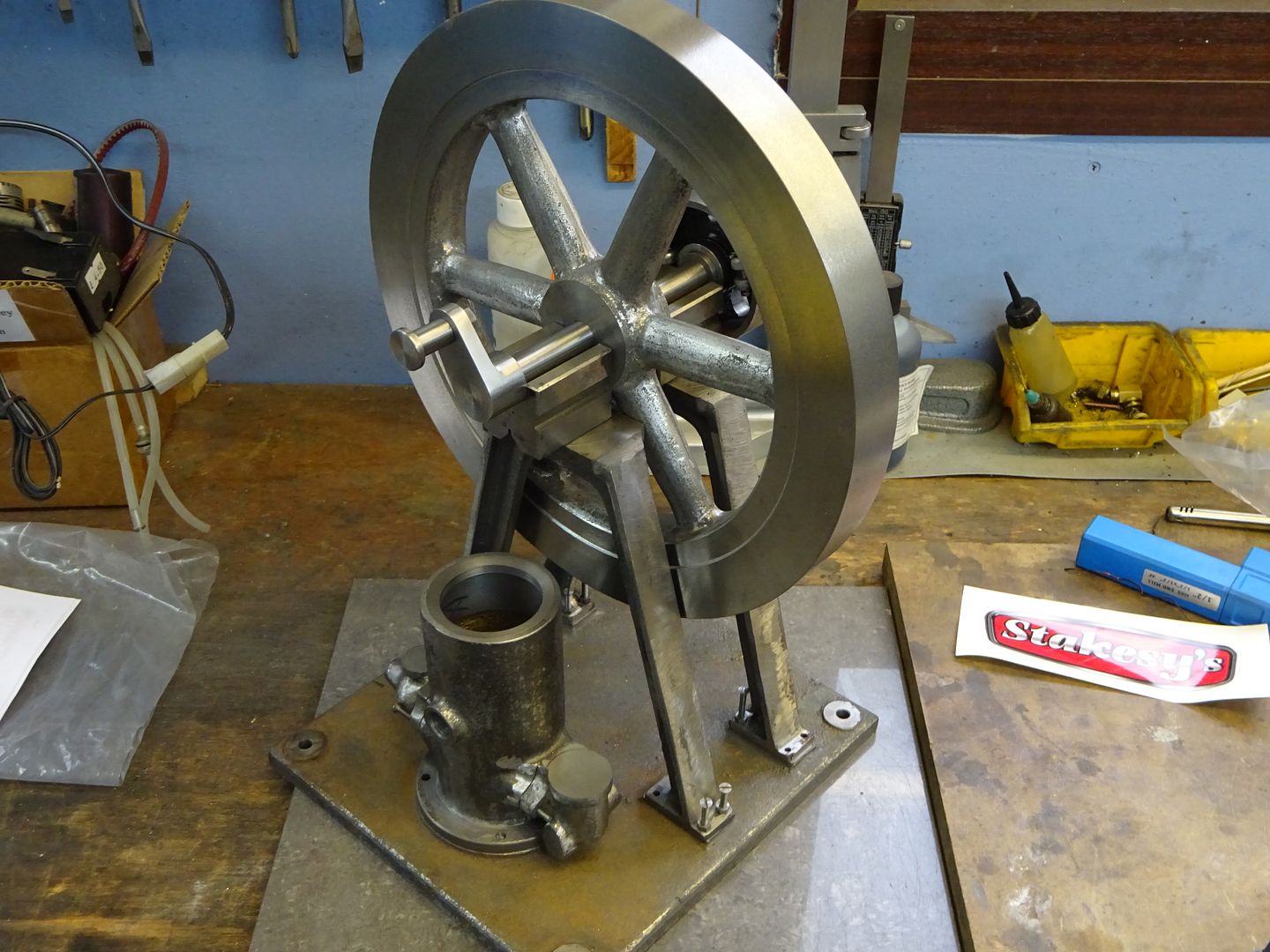
| JasonB | 13/09/2018 06:54:13 |
 25215 forum posts 3105 photos 1 articles | It is a bit of a beast with that thick rim, the previous Allman engine that I built ran for quite a while and this one is heavier |
| mechman48 | 13/09/2018 17:57:27 |
 2947 forum posts 468 photos | Super bearing fit there Jason. |
| Ian Hewson | 13/09/2018 20:03:31 |
| 354 forum posts 33 photos | Still don’t know how Jason fits it all in to a day, I feel tired imagining how he does it👍 |
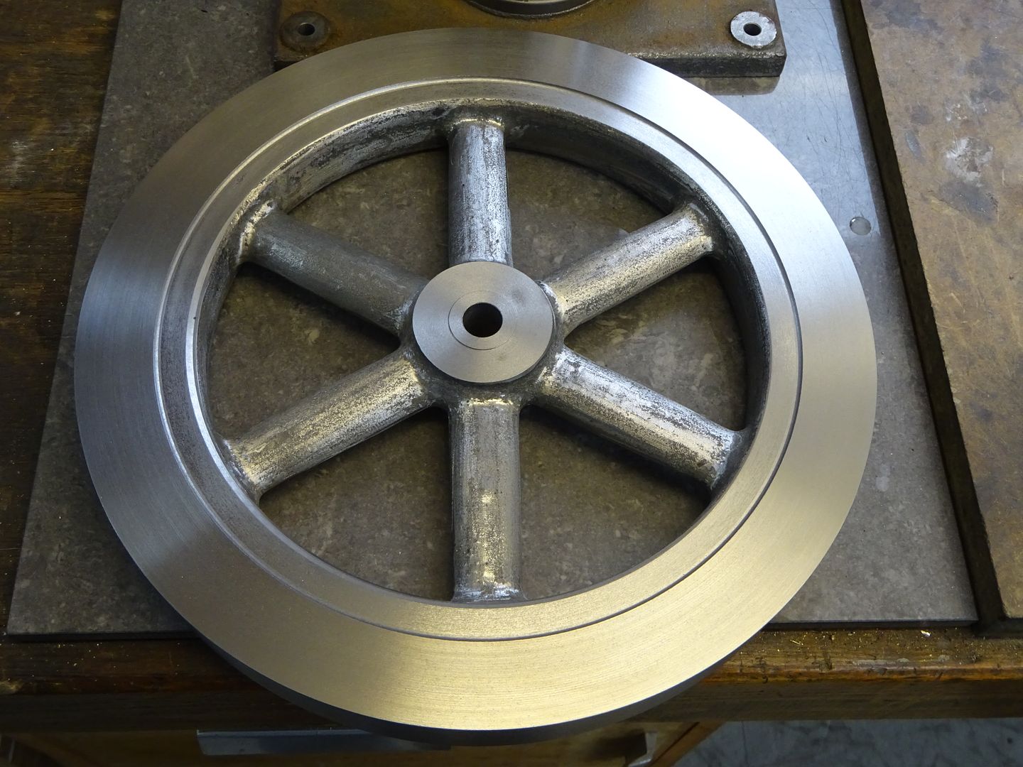
| JasonB | 15/09/2018 07:35:11 |
25215 forum posts 3105 photos 1 articles | Made a start on the IF Allman flywheel yesterday, should get it finished today, seems more like SG iron than a nice grey iron but is not machining up too badly. At 10.5" it is right on the limit of my 280, to start with the rough casting was just kissing the yellow carrage legs so had to have quite a bit of tool overhang hence the inverted boring bar and running in reverse ( don't try that with a screw on chuck) |
| Ian S C | 15/09/2018 14:19:33 |
 7468 forum posts 230 photos | I have another lathe tool similar to this one, but right hand at one end and left hand at the other, and it gets used as your boring bar is, except that the tool is the right way up, and the lathe is turning forward (screw on chuck). Ian S C |
| JasonB | 15/09/2018 20:07:48 |
25215 forum posts 3105 photos 1 articles | Ian, I do also have a L/H tool for my usual CC** insert but as I don't use the L/H very often I only have a 6mm Sq one and that would have sung a bit with 80mm sticking out teh tool post so I went with teh more substantial boring bar. All machining finished now just a little bit of grinding work and a keyway to broach.
|
| mechman48 | 16/09/2018 14:12:44 |
2947 forum posts 468 photos | Another little contribution of my Boxer twin, marked out for the cylinder blocks. Pic 1 is marked out for one then the light went on, turned it round & marked for both blocks, obviously it will be split down the middle & the dimensions are such that there is enough room for machining. I plan on setting it up in 4 jaw then drill to 9mm then bore out to reaming size for 11mm, split down middle & finish machining to leave 5.5 radius to fit cylinders & solder… |
| Brian O'Connor | 18/09/2018 15:38:52 |
| 74 forum posts 19 photos |
Just finished the Cam Gear Bracket for my Star hit&miss engine. It started out as a 3in x 3in x 1.5in block of cast iron. It now weighs less than 10% of its original weight. Bucket of swarf, anyone? B |
| Muzzer | 18/09/2018 15:59:17 |
 2904 forum posts 448 photos | Nice work, Brian - do you have a DRO on the mill or was this painstaking manual positioning? And looks like a rotary table for the top feature? Murray |
| geoff walker 1 | 18/09/2018 17:27:30 |
| 521 forum posts 217 photos | Yes, very nice, as someone once said it's amazing what you find inside a big chunk of cast iron. Hope you had a good clean up Brian!!!! Geoff |
| Jim Nic | 18/09/2018 21:08:38 |
406 forum posts 235 photos | Whatever that started out as Brian, and whatever it has ended up as, it is a very good looking piece of hardware which clearly took a lot of skill and care to make. Jim |
| Mike Poole | 18/09/2018 21:25:15 |
 3676 forum posts 82 photos | Nice job Brian, bet your glad you didn’t have to saw and file it Mike |
| Brian O'Connor | 18/09/2018 23:05:31 |
| 74 forum posts 19 photos | Thank you all for your kind comments. I think that this was the most stressful bit of machining that I have ever done. I didn't have an image of the finished piece, only (American) drawings so I spent a lot of time thinking about what it would look like and how I was going to tackle making it. I was terrified of screwing up at every stage, it's so easy to turn the wrong wheel ot turn it the wrong way. I do have DROs on mill and lathe and don't know how I would have managed without them. I also made extensive use of my centring microscope (Hemingway kit - well worth making). Murray. For the top feature (the support for the governor) I turned the top bit on the lathe with it held in the 4-jaw but had to file the lower part. |
| mechman48 | 19/09/2018 09:25:34 |
2947 forum posts 468 photos | Modified spare fly wheel for my Boxer. It was originally for a gyroscope toy that still is on the back burner for some reason, had to make a new boss & solder it in to allow for drilling & tapping for locking grub screw as the web is too thin to drill through from the rim ( according to drawing dims' )… |
| Ian P | 19/09/2018 10:39:03 |
 2747 forum posts 123 photos | Posted by Brian O'Connor on 18/09/2018 15:38:52:
Just finished the Cam Gear Bracket for my Star hit&miss engine. It started out as a 3in x 3in x 1.5in block of cast iron. It now weighs less than 10% of its original weight. Bucket of swarf, anyone? B 'Cam Gear Bracket' nowhere near describes what is obviously a beautiful piece of workmanship. There a brackets and there are brackets, but this one is doing a lot more holding than any other bracket I have seen! Ian P |
| mechman48 | 21/09/2018 17:34:49 |
2947 forum posts 468 photos | Machined up & reamed the cylinder blocks before splitting into separate items & machined chamfers in prep for soldering. Inlet ports have been marked off & drilled through blocks so after soldering to cylinders the ports will be drilled through cylinder wall to ensure alignment... methinks... |
| David Taylor | 22/09/2018 09:48:13 |
 144 forum posts 39 photos | I spent a lot of the non-work week planning and making these brake shoes. They still need their inside edges rounding off the clear the flange root and the hanger slots probably need to be deeper but I might just do that with a file as I don't have a suitable endmill or slitting saw.
Regards, David. |
| Alan Vos | 22/09/2018 16:28:47 |
| 162 forum posts 7 photos | Posted by Brian O'Connor on 18/09/2018 23:05:31:
I think that this was the most stressful bit of machining that I have ever done. I didn't have an image of the finished piece, only (American) drawings so I spent a lot of time thinking about what it would look like and how I was going to tackle making it. You may wish to consider investing some time in 3D CAD. Numerous free options available (see other threads). I use Fusion 360. With that you could use the drawings to produce the 3D shape. Then start over with a solid block and subtractive cuts to simulate a machining sequence. |
| David Taylor | 23/09/2018 00:21:37 |
144 forum posts 39 photos | Really nice Brian - I can well imagine the stress of making that appear from a solid block but you've done it! |
.jpg")
.jpg")
.jpg")


.jpg")
.jpg")


This thread is closed.
Magazine Locator
Want the latest issue of Model Engineer or Model Engineers' Workshop? Use our magazine locator links to find your nearest stockist!
Sign up to our Newsletter
Sign up to our newsletter and get a free digital issue.
You can unsubscribe at anytime. View our privacy policy at www.mortons.co.uk/privacy
Latest Forum Posts
- hemingway ball turner
04/07/2025 14:40:26 - *Oct 2023: FORUM MIGRATION TIMELINE*
05/10/2023 07:57:11 - Making ER11 collet chuck
05/10/2023 07:56:24 - What did you do today? 2023
05/10/2023 07:25:01 - Orrery
05/10/2023 06:00:41 - Wera hand-tools
05/10/2023 05:47:07 - New member
05/10/2023 04:40:11 - Problems with external pot on at1 vfd
05/10/2023 00:06:32 - Drain plug
04/10/2023 23:36:17 - digi phase converter for 10 machines.....
04/10/2023 23:13:48 - More Latest Posts...
- View All Topics
Support Our Partners


Shopping Partners
Subscription Offer

Latest "For Sale" Ads
- Reeves** - Rebuilt Royal Scot by Martin Evans
by John Broughton
£300.00 - BRITANNIA 5" GAUGE James Perrier
by Jon Seabright 1
£2,500.00 - Drill Grinder - for restoration
by Nigel Graham 2
£0.00 - WARCO WM18 MILLING MACHINE
by Alex Chudley
£1,200.00 - MYFORD SUPER 7 LATHE
by Alex Chudley
£2,000.00 - More "For Sale" Ads...
Latest "Wanted" Ads
- D1-3 backplate
by Michael Horley
Price Not Specified - fixed steady for a Colchester bantam mark1 800
by George Jervis
Price Not Specified - lbsc pansy
by JACK SIDEBOTHAM
Price Not Specified - Pratt Burnerd multifit chuck key.
by Tim Riome
Price Not Specified - BANDSAW BLADE WELDER
by HUGH
Price Not Specified - More "Wanted" Ads...
Get In Touch!
Do you want to contact the Model Engineer and Model Engineers' Workshop team?
You can contact us by phone, mail or email about the magazines including becoming a contributor, submitting reader's letters or making queries about articles. You can also get in touch about this website, advertising or other general issues.
Click THIS LINK for full contact details.
For subscription issues please see THIS LINK.
Digital Back Issues


Donate

 Register
 Log-in
Model Engineer Magazine
- Percival Marshall
- M.E. History
- LittleLEC
- M.E. Clock

ME Workshop
- An Adcock
- & Shipley
- Horizontal
- Mill

Subscribe Now
- Great savings
- Delivered to your door

Pre-order your copy!
- Delivered to your doorstep!
- Free UK delivery!
All Forum Topics > Work In Progress and completed items > The Workshop Progress thread 2018