Forum sponsored by:

5 CC CI engine (and a bit of a Grump)
| Ramon Wilson | 06/10/2011 14:04:34 |
 1655 forum posts 617 photos | Hi John, Jason,
One can understand why draughtsmen had 'checkers'
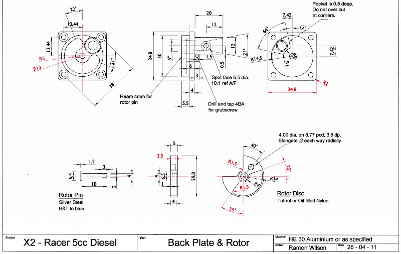
 - despite looking at the crankcase drawing and updating the length and position I still missed the thickness. - despite looking at the crankcase drawing and updating the length and position I still missed the thickness.It's 4.5mm John and yes I will post any updates on here.
Thanks for pointing out the ommision on the rotor disc too Jason. Again, I checked this drawing the other night and noticed the width of the backplate as 34.5 - it should of course be the same as its height - 34.8.
The lower angle is 35 degrees from the vertical and the upper angle is 20 degrees from the horizontal. This is just a pocket for lightness and a degree of balance - the actual dimensions are not particularly critical. The inlet cut out itself is 90 degrees which should be as accurate as possible as this and the pocket in the backplate itself is what defines the inlet timing.
I have just noticed another small anomaly. The inlet cut out is shown with a sharp corner at the top and a radius at the bottom. This should have radii on both corners - the original was cut with a 3mm cutter
I hope that those who may feel this should have been a bit more accurate will take into allowance that these were my first attempts using Autocad having used nowt but a pencil afore. Not an excuse, but the circumstance.
Original drawings are duly updated.
Hope this helps John - are you cutting yet?
Regards - Ramon
|
| Ramon Wilson | 06/10/2011 23:42:40 |
1655 forum posts 617 photos | Here are the updated Crankcase and Backplate drawings - all updates in red
For some reason the scanner has not picked up the borders but no information has been missed

I believe the future instalments have already been dealt with - so any further errors, and I have found one or two - no doubt Jason's keen eye will spot any others missed - will be updated as they appear.
This reminds me that several years ago during the period I was working on press tools we had a designer - 'RJJ' - who was (in)famous for his mistakes. He would swiftly run a pen through - no cad then - and with a dismissive flourish hand you the drawing back with a well versed "Sorry about that". It soon became a catch phrase in the tool room and we had a rubber stamp made with the legend 'A genuine RJJ 'Sorry about that'. Great delight was taken to ensure drawings were duly stamped 'when required' and though he gave the impression he was taking it in good fun it obviously irritated. We all thought it hilarious of course but it was rather short lived as despite his ferret like but unsuccessful searching for it for several days he suddenly came upon it by chance when one of us in a lax moment let our guard down. His triumph had to be seen to be appreciated and it quickly deflated our little game. 'Well bless our souls, we said, that splendid chap Richard has just found our stamp' or was it something rather similar
 I hope I don't have too many 'Sorry about that's'
Regards for now - Ramon
Edited By Ramon Wilson on 06/10/2011 23:44:23 |
| Bill Pudney | 07/10/2011 04:02:46 |
| 622 forum posts 24 photos | Don't fret about missing drawing "whoopsies" Ramon. When I was a Draftsman I found it close to impossible to spot my own mistakes. We used to add 30% as a "checking allowance" to D.O. estimates. One prototype project I was involved in was creating a huge amount of grief from the Workshop Manager, he was saying that my drawings were no good and full of errors. Purely in my own defence I went through each of about 200 drawings, added up all the dimensions and compared them to the known errors. The actual error rate was under three percent. At the time in the standard (DEF AUS 5085 I seem to remember) the permitted error rate was five percent. As the Workshop Manager had been spreading my perceived incompetance up to CEO level, I took some pleasure in writing a memo to the person concerned and copying it to my boss and the CEO to explain the facts. No more problems!! cheers Bill Pudney Edited By Bill Pudney on 07/10/2011 04:03:51 |
| Richard Parsons | 07/10/2011 10:13:33 |
 645 forum posts 33 photos | I am not going to throw teddy out of the pram but I have a touch of the ‘Grump’ again. The machining of the crankshaft is described but NO finished dimensions given (yet). I have to order a 7mm reamer from a local supplier. What else do I need? Raymond In view of the scuffing you found and the fact that you are trying to reproduce an engine from the late 1940s early 50s I understand your design. I do not want to re create anything I am going to build a 5CC diesel based on your design. My first change will be to use an oil seal (SOG 102711 8 22 7 2) outboard (on the propeller side) of the main 7mm race to maintain crankcase compression. My second change will be to use a ring of holes (of a suitable size) as transfer ports. Raymond would you (and anyone else) care to comment. |
| David Clark 1 | 07/10/2011 10:44:53 |
 3357 forum posts 112 photos 10 articles | Hi There
The reamer is not required.
I have just looked at the drawing going into 4415 and it is a 1/4 reamed hole. Not 7mm as Ramon has stated in the text.
The 7mm is the counterbore that is stated in the text as 7.5mm.
regards david
|
| Ramon Wilson | 07/10/2011 12:10:55 |
1655 forum posts 617 photos | Hi Guy's
Oh dear I really have mislead you here I'm afraid - well sort of.
When I built my two engines and indeed the Etas too I did ream the main shaft 7mm thru with a short 2mm deep 7.5mm counterbore for 6.35 finished shafts. The inner shaft was made to suit and, as stated in the text, the whole lot was turned between centres after Loctiting. When I drew it in Cad I must have overlooked that fact and drew it as shown. I certainly didn't realiise it conflicted with the text
However I'm certain that providing the inner shaft is made accurately before Loctiting and is a good fit in the main shaft there should be no problem with concentricity.
The easiest way around it, though not an ideal way of going about things, would be to change the design slightly and keep to reaming 6.35 through and reducing the front end to 6mm between centres making sure you remember to ream the collet 6mm and thread the spinner nut M6 too. This will be more than adequate - the Eta Mk 1 has a 6mm (as designed) front end and is running well.
Dick you really should not need to put a seal behind the front bearing to maintain crankcase pressure. The scuffing was probably due to some miniscule bit of debris that allowed the shaft to pick up. I have not experienced the problem before or since - in any engine. It is usual to allow the fuel to reach the front bearing by allowing a degree of leakage down the shaft. Though both Racers have open bearings at the front I have removed the inner seal on some front bearings to prevent ingress of dirt but allow lubrication from the rear. As far as two stroke diesel and glowmotors are concerned I have never seen a seal being used.
The drilling of holes for the transfer ports instead of radial slots should be okay but I would imagine the performance may possibly drop off a bit due to the opening being gradual. That said several designs feature this kind of porting so don't perceive it as a great deviation. Drilling the holes at an angle towards the top of the bore however will increase the transfer period - just as in the Eta's
Bill - Thank you for your kind words of reassurance. I do realise that despite trying my damndest mistakes will happen - it's just not nice when you realise others are relying on you not to make any
This is fast becoming a salutory lesson. It is the first time I have had a design published and can see that far more care will be required should anything materialise in the future. All I can say - promise - is that I will take note and update the drawings as and when required.
Finally Dick could I just say that my name - Ramon - was not of my choosing, that was defintely beyond my control, but it is my name and that's the way it's spelt. I have had several nicknames over my years the ubiquitous 'Tug' being the usual but I don't refer to it on here. That said however I'm definitely not a 'Raymond' either
. Regards to all - Ramon
Edited By Ramon Wilson on 07/10/2011 12:12:09 |
| David Clark 1 | 07/10/2011 14:12:54 |
3357 forum posts 112 photos 10 articles | Hi There
We all make mistakes.
Even Martin Evans was known as Martin Errors.
In 5 years time you will be turning out perfect designs.
regards David
|
| Richard Parsons | 07/10/2011 15:43:56 |
645 forum posts 33 photos | Ramon, Sorry I was not looking at the web-site when I wrote my little bit. Your comment about the use of an oil seal being somewhat unusual is odd to my mind. Since I came over to Hungary I have almost ‘made a corner’ in repairing 2-stroke chain saw and strimmer engines. Hungarians are the world’s greatest wizards at breaking things. All of these have oil seals in them. So I am going to try them here. I now have about enough information from your postings to refigure the transfer ports. Your suggestion of drilling them at an upward angle seems good but I will only do so in those regions of the cylinder which do not face an exhaust port. Those holes will be at Right Angles to the bore. This will direct the fresh gasses into the centre where of the cylinder the ‘pent headed’ piston directs gasses upward. The idea is to avoid losing too much of the fresh charge and getting rid of the spent gasses. When I have lapped in the piston I want to hear a descent ‘pop’ when the transfer ports open. This means minimising the dead space in the crank case. As to nick names I have had many including ‘Chewy’ aka ‘Chewbacca’ I was very large and hairy! Rgds Dick |
| Ramon Wilson | 07/10/2011 17:29:45 |
1655 forum posts 617 photos | Five years David? that's a lot of engine building time - I hope it doesn't take that long to get to a decent stage
 Dick - I was refering to small model aircraft engines - well up to 10cc as I've no experience with anything larger.
I didn't realise you were thinking of adding 'extra' porting between exhaust areas - it will be interesting hear if your results provide an increase in performance.
I have to stress I have no 'scientific' background on these small engines other than having operated them in various forms over many years. It's only in recent years that the 'internals' have been of interest to me but I'm at the bottom of a very long stairway as far as these inner workings are concerned.
Something I have pondered over however is that some engines have - relatively - enormous passages cast or cut in the case to get the fuel up to the actual transfer passages cut through the liner. This leads me to think that as this must increase crankcase volume it must also have an effect on lowering case pressure which is what takes the fuel through. Whilst sufficient fuel obviously needs to transfer surely doing this at a higher pressure, obtained by keeping the case volume to a minimum is a benefit. The actual (case) passages on the Racers though quite wide are relatively narrow just .5mm but appear to give more than sufficient fuel at higher revs.
Anyone with any thoughts on this matter?
Regards - Ramon
|
| Ramon Wilson | 23/10/2011 19:43:49 |
1655 forum posts 617 photos | Hi 'Guy's'
I have just had an email from someone making this engine pointing out another omission this time on the Liner and Piston drawing.
The overall dimension over the exhaust flange is 26.0mm and the outer diameters top and bottom are 22.0 to fit both the case and cylinder barrel (fins). It's ideal to have the fit in the barrel a nice tight but slide fit for better heat transfer but that in the case can be eased some what. If anyone decides to shrink fit the fins on the liner remember that that will in all probability distort the liner so the lapping would need to be done after such fitting. Given the likely use of this engine though I feel to fit the fins in such a manner is totally unneccessary.
Finally a reminder that simple En1a free cutting steel is perfectly adequate for this component if the engine is not going to be used on a regular 'working' basis ie fitted to a model and flown though even then it will last quite some time.
Although this material is mentioned in the text I have not drawn attention to the fact that the last three Eta engines used En1a and the piston liner fits in those are bedding in superbly and it is something I will certainly use again in the future.
Liner and Piston drawing duly updated.
 Apologies for the ghosting on the cutter area - can't understand why that's happening at the moment but the salient bits are clear enough!
And yes - once again, another 'Sorry about that' is due Regards - Ramon
|
| Stub Mandrel | 25/10/2011 21:05:54 |
 4318 forum posts 291 photos 1 articles | Ramon, Your cutters are things of delicate beauty, so I hate to criticise, but for similar tools I don't bother with side clearance, or if I do just machine the disc from which the cutter is made slightly concave. Instead of your elegant curved backs, i just mill across at an angle to leave the slightest witness behind the cutting edge. 'Works for me' Neil 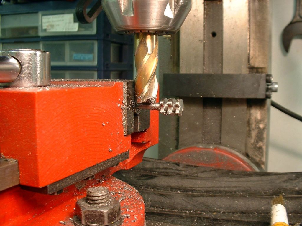 Here's a nice big endmill making a little three-gang cutter (to an ETW design). And proof it works: 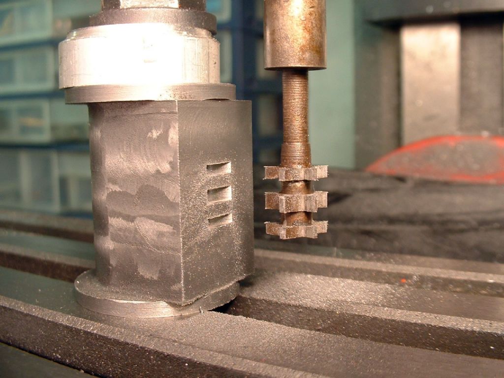 Edited By Stub Mandrel on 25/10/2011 21:07:39 |
| Ramon Wilson | 25/10/2011 22:55:30 |
1655 forum posts 617 photos | Hi Neil,
Yes I know where you're coming from and indeed thats how I set out on these cutters originally. I dished them both sides thinking that that would be sufficient clearance after all it's only the very tips that are doing the cutting. I think the problem here was mainly due to the thin nature of the cutter and not enough meat to allow a sufficient clearance angle.
However those first two just rubbed and wore so quickly and did in fact spoil the first (steel) cylinder (not referred to in the text!). The last, as said sailed through with ease however the fact that it was left hard - ie not tempered - as well as backed off probably improved matters as well.
As drawn it is, I confess, a bit of artistic licence without realising the implications. This is how they were actually made the bottom right hand one being the one that worked very well - still usable infact
 Hmmm, I've only just realised that I drew them with three teeth and made them with five
Thanks for your input though - all noted for any future drawings
Regards - Ramon |
| methusala | 26/10/2011 10:37:36 |
| 32 forum posts | Hi Ramon, Hmmm, I've only just realised that I drew them with three teeth and made them with five.  I would have a recount if I were you . I would have a recount if I were you . |
| Ramon Wilson | 26/10/2011 10:58:53 |
1655 forum posts 617 photos | Hmmm, infact double *&^%* Hmmm
Attention to detail that's my motto
- well it used to be, I'm just getting bloody old and I don't sodding like itDoes any one else have moments like these - they're getting a bit too frequent for my liking - oh well just keep smiling
Regards - Ramon |
| Clive Hartland | 26/10/2011 11:06:00 |
 2929 forum posts 41 photos | As said, 'Keep taking the pills and smile'.
Dont let the detail get you down Ramon, you did good and its published and as always something is found by people, that you took for granted and they make an exception!
Clive
|
| methusala | 26/10/2011 20:55:09 |
| 32 forum posts | I'm sorry Ramon I didn't mean to offend you, Please accept my apologies, No you are not alone, I know that I do the same sort of thing on a regular basis , and I'm sure others do as well. |
| Steve Withnell | 26/10/2011 21:33:43 |
 858 forum posts 215 photos | I tell you what, this thread has convinced me never to submit anything for publication! |
| Ramon Wilson | 26/10/2011 22:24:35 |
1655 forum posts 617 photos | Colin,
Please - absolutely no need to apologise and absolutely no offence taken I assure you - really. Indeed I couldn't believe what I'd written once you'd pointed it out.
 That was exactly my point - It really does surprise me as to just how much slips me by these days - I had a true Classic with 'Wheeltappers' Nemmet 15
- Better have a good laugh I'm sure others will be. Seriously though I do find it becoming more and more impossible to keep even a couple of balls in the air these days - at one time it was several - honestly - but I'm definitely quite adept at dropping them these days. Thanks for your words of suppport though Clive, I am from the school that says 'must try harder' though but I'm beginning to feel less and less like beating myself up about it.
Steve - don't let anything put you off - nobody's beating my door down and despite what you might think it has been well worth it. I know just how I'm going to feel if just one engine gets built and whoever makes it gets as big a thrill as I did when it runs
I've finally got back onto the lathe today - it's been a fair break - first off is a new, larger saddle handwheel for the Myford and then some work on the Waller engine
Off to bed with a big smile on my face then and looking forward to tomorrow
Regards for now - Ramon
Edited By Ramon Wilson on 26/10/2011 22:29:59 |
| Andrew Johnston | 28/10/2011 09:05:31 |
 7061 forum posts 719 photos | Posted by Steve Withnell on 26/10/2011 21:33:43: I tell you what, this thread has convinced me never to submit anything for publication! That's a shame, I'm sure it would be an interesting read. Regards, Andrew |
| Ian S C | 28/10/2011 10:56:20 |
 7468 forum posts 230 photos | Never say never! Ian S C |
Please login to post a reply.
Magazine Locator
Want the latest issue of Model Engineer or Model Engineers' Workshop? Use our magazine locator links to find your nearest stockist!
Sign up to our Newsletter
Sign up to our newsletter and get a free digital issue.
You can unsubscribe at anytime. View our privacy policy at www.mortons.co.uk/privacy
Latest Forum Posts
- hemingway ball turner
04/07/2025 14:40:26 - *Oct 2023: FORUM MIGRATION TIMELINE*
05/10/2023 07:57:11 - Making ER11 collet chuck
05/10/2023 07:56:24 - What did you do today? 2023
05/10/2023 07:25:01 - Orrery
05/10/2023 06:00:41 - Wera hand-tools
05/10/2023 05:47:07 - New member
05/10/2023 04:40:11 - Problems with external pot on at1 vfd
05/10/2023 00:06:32 - Drain plug
04/10/2023 23:36:17 - digi phase converter for 10 machines.....
04/10/2023 23:13:48 - More Latest Posts...
- View All Topics
Support Our Partners


Shopping Partners
Subscription Offer

Latest "For Sale" Ads
- Reeves** - Rebuilt Royal Scot by Martin Evans
by John Broughton
£300.00 - BRITANNIA 5" GAUGE James Perrier
by Jon Seabright 1
£2,500.00 - Drill Grinder - for restoration
by Nigel Graham 2
£0.00 - WARCO WM18 MILLING MACHINE
by Alex Chudley
£1,200.00 - MYFORD SUPER 7 LATHE
by Alex Chudley
£2,000.00 - More "For Sale" Ads...
Latest "Wanted" Ads
- D1-3 backplate
by Michael Horley
Price Not Specified - fixed steady for a Colchester bantam mark1 800
by George Jervis
Price Not Specified - lbsc pansy
by JACK SIDEBOTHAM
Price Not Specified - Pratt Burnerd multifit chuck key.
by Tim Riome
Price Not Specified - BANDSAW BLADE WELDER
by HUGH
Price Not Specified - More "Wanted" Ads...
Get In Touch!
Do you want to contact the Model Engineer and Model Engineers' Workshop team?
You can contact us by phone, mail or email about the magazines including becoming a contributor, submitting reader's letters or making queries about articles. You can also get in touch about this website, advertising or other general issues.
Click THIS LINK for full contact details.
For subscription issues please see THIS LINK.
Digital Back Issues


Donate

 Register
 Log-in
Model Engineer Magazine
- Percival Marshall
- M.E. History
- LittleLEC
- M.E. Clock

ME Workshop
- An Adcock
- & Shipley
- Horizontal
- Mill

Subscribe Now
- Great savings
- Delivered to your door

Pre-order your copy!
- Delivered to your doorstep!
- Free UK delivery!
All Forum Topics > I/C Engines > 5 CC CI engine (and a bit of a Grump)