Forum sponsored by:

A QCTP question, or two
| Bazyle | 24/12/2015 10:47:11 |
 6956 forum posts 229 photos | Chris, if it helps Chronos are doing Myford size Soba holders at about £11 at the moment in 5 off quantity. Haven't tried one for fit yet but the post was from the same source so interchangeability should be less of an issue. An interesting point in a way as I've never thought of bluing one to check on contact area. BTW not advising it necessarily but I use a Myford size on a 4 1/2 Boxford on a 1/4 raising plate. At the time I didn't have anything to compare so did not know I had been given the wrong size until I came to buy more holders. At least it makes the holders cheaper and I'm not making parts for battleships anyway so plenty rigid enough. |
| Vic | 24/12/2015 12:10:24 |
| 3453 forum posts 23 photos | Tim, you may find this of interest. RDG do a five piece set starting at £84 inc. not worth making at this sort of price? http://www.rdgtools.co.uk/acatalog/Quick_Change_Toolposts__Complete_Sets_.html Edited By Vic on 24/12/2015 12:30:26 |
| Tim Stevens | 24/12/2015 14:53:25 |
 1779 forum posts 1 photos | M Gillingham says: ... I think you will find that pushing loose-fitting male/female dovetails into engagement [by pressure at about the mid-point] will automatically centralise them ... It would be worth doing a few practical tests on your QCTP. In an ideal world this would be expected, but I have doubts about the bits I have. The central plunger is not very wide, so it has little centralising influence. I can hold the parts in my hand with light pressure on the cam arm, and the toolblock can, in effect, swivel around from touching one side of the angle faces to the other. I fear that under side pressure on the tool this is likely to be what happens. Clearly the Dickson type is better in this respect as the end of the toolblock carries a 90 degree V groove which locates the block definitely. Thanks everyone for shining some light into the dark corners of my understanding. Don't drink too much, or too little, do you hear? Regards, Tim |
| NJH | 24/12/2015 14:55:05 |
 2314 forum posts 139 photos |
For Vic's benefit- but maybe of interest to others also here are some pictures of my rear tool post QC parting arrangement.
As you can see it is a substantial item and fits firmly to the cross slide by a three point attachment. It does need to be the long version cross slide to get it all on and still leave room to work. If not carrying out parting on a particular time the tool can be removed or maybe a chamfering tool could be added to ( yet another ) toolholder. As far as the source of the tool holders they are either Myford originals or Chronos I think. ( Always a useful item for those who don't know what to buy you for xmas etc.) As KWIL says if you are going to have quick change tooling ( and I certainly recommend it !) then there is no point in economising on the number of holders or it becomes "not so fast change"! I'm not so sure about 52 holders though ! That risks becoming "Quick Change Once You Can Find It " ( In my workshop anyway !) Norman
Edited By NJH on 24/12/2015 14:57:42 |
| Clive Foster | 24/12/2015 15:49:24 |
| 3630 forum posts 128 photos |
A great advantage of the Dickson type is that its very easy to keep clean. All the mating surfaces can easily be got at to brush stray chips away before mounting a new tool. Its also very easy to pull the locking system out to clean and very lightly lubricate for smooth, accurate operation. Probably worth doing every year or so, maybe more often if you do much brass work. I'm always amazed by how much stuff manages to find its way into mine over the course of a year. Its not as if there are huge gaps for chips to fly through and things are fairly well shielded from direct flight anyway. If chips do build up the grip of post on holder drops dramatically. When all is clean it doesn't take that much pull on the lock to hold things nice'n stable. So if you find your self heaving on the spanner to stop tooling shifting under heavy cuts its time to make with the pinny and rubber gloves or rather the workshop equivalent. Looking through the latest MEW about 39 seconds after it flopped through the letterbox today I saw that fitting a roller thrust bearing under the tool post holding nut was suggested as a palliative to the hauling up real tight to stop the tool post turning issue. If a QC tool post rotates under cut unless heaved up really tight odds are that the top of the topside has been distorted by such heaving so the problem can only get worse. Quick and dirty cure is a thin card or alloy shim under the tool post to spread the clamping load. Proper fix is to ensure that the top of the slide is flat and that the tool post has a shallow relief in the bottom to ensure that the clamp load is applied via the out per part of the post rather than right in the middle. Obviously if contact is made towards the outside there is more leverage to stop the post turning under cutting loads than if the main contact is close to the centre. If the top slide is distorted by over tightening the top nut it will tend to pull up most around the stud concentrating gripping forces around the centre where they are least effective. Probably a circular relief 50 thou / 1 mm or so deep of diameter around half the width of the tool post will be effective but its hardly critical. I'd still keep the card or alloy shim tho' . No way of getting around the fact that any tool mounted in a QC post has to divine its support at considerable distance so there is plenty of leverage to shift things. Smaller units are disproportionally less stiff too which doesn't help in our sizes. Clive.
Edited By Clive Foster on 24/12/2015 15:50:09 |
| Michael Gilligan | 24/12/2015 16:22:07 |
 23121 forum posts 1360 photos | Posted by Tim Stevens on 24/12/2015 14:53:25:
... In an ideal world this would be expected, but I have doubts about the bits I have. The central plunger is not very wide, so it has little centralising influence. I can hold the parts in my hand with light pressure on the cam arm, and the toolblock can, in effect, swivel around from touching one side of the angle faces to the other. I fear that under side pressure on the tool this is likely to be what happens. . Sorry to hear that, Tim MichaelG. . P.S. ... No offence taken, but; Gillingham is a town in Kent |
| Vic | 24/12/2015 17:01:03 |
| 3453 forum posts 23 photos | That's a very nice set up Norman. If you get the chance have a look at the "T" shape parting blades that Chronos sell, they work very well. Clive, it's hard sometimes to appreciate just how good the Dickson design is until you compare it to how some of the lesser designs out there work. The Dicksons we had at work had a "stop" pin and corresponding hole in the top slide to prevent rotation. Easily raised to allow any angle of the tool post if required. The pin itself was always a lovely sliding fit in the tool post. You can see the pin in this picture.
Edited By Vic on 24/12/2015 17:15:11 |
| Speedy Builder5 | 24/12/2015 19:04:42 |
| 2878 forum posts 248 photos | I have an ELLIOT S.00 HB QCTP system which has imperial cams and pins. Some time ago, I bought a spare pin and camb, but they were metric dimensioned and the wrong size ! Looking on the internet, how would I know which holders to go for as I assume some will be metric and some imperial. |
| mechman48 | 24/12/2015 19:21:28 |
 2947 forum posts 468 photos | ... 'If a QC tool post rotates under cut unless heaved up really tight odds are that the top of the topside has been distorted by such heaving so the problem can only get worse. Quick and dirty cure is a thin card or alloy shim under the tool post to spread the clamping load. Proper fix is to ensure that the top of the slide is flat and that the tool post has a shallow relief in the bottom to ensure that the clamp load is applied via the out per part of the post rather than right in the middle'... When I modified my WM250 to take a QCTP I made sure that the top surface was given a scraping to mate with the tool post over the majority of the slide plus the added advantage of having the anti rotation pin fitted for two positions. George. |
| CotswoldsPhil | 24/12/2015 19:46:01 |
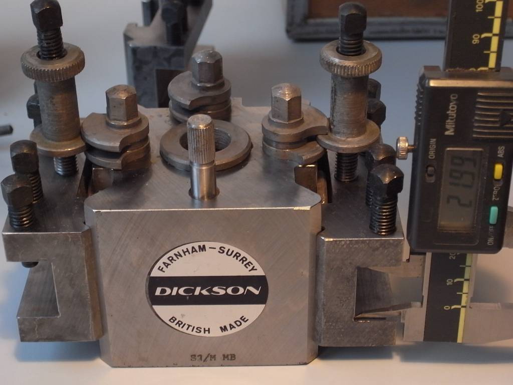
 196 forum posts 112 photos | Hi All, Prompted by this latest thread on QCTP compatibility issues, here is my experience of trying to find compatible holders to extend my usage of QCTH's at reasonable cost. I have measured the relative position of the V seating to the working face of the locking t-slot of 11 Myford (T00) sized holders of different brands which I have purchased over the last year. My aim was to try and establish the most compatible pattern holder for my set-up at the least cost. I appreciate that my measurement set-up (see photo below) is not to national standards, but it was repeatable.
The 2 holders which came with the Bison/Toolmex tool-post (and started this whole saga) were used as the reference point i.e. zero. These holders positively locked at approximately 50% on the clam-shell height adjuster. (all measurements shown below are + values in imperial units) I have 3 holders sourced from the Midlands Exhibition last year; stamped "M" or "W" these gave relative measurements of 0.013, 0.008 and 0.012 providing reduced locking positions of 25,30 and 25% and just about OK, i.e. reasonably positive. I took a punt on a 26mm / 2mm Carbide Parting Blade holder (HBM brand) from RDG and this measures 0.007 with a very positive 40% lock position. This holder has sorted all my parting-off woes - very pleased. Based on this positive experience, I purchased a HBM HSS parting tool holder (for use as a screw-cutting tool with minimum grinding) This measured 0.020 with a not very positive 10% lock position. Another HBM standard holder measured 0.023 with a not very positive 10% lock position. Another HBM 1/2 inch tool holder, measured 0.015 with a not very positive 15% lock position, especially important as it is designed to hold a larger tool at centre height on the Myford. These 3 holders are obviously made for the HBM tool-post but there is still a wide variation in my sample. Foxed again; I took a punt on 2 holders from Axminster Tools (turned out to be SOBA brand when received), these proved to be even less compatible measuring 0.024 with hardly any locking action, and a whopping 0.038 with no locking action at all. Again these are designed to go with the SOBA tool-post but my very small sample, showed quite a large variation for a precision product. All these additional holders are nicely hardened and ground but the variation is very wide, even within the same brand. So, I have now collected 11 holders, of which, 6 are usable in my workshop, I'm really thinking I should go back to the 4 way tool-post and be done with it! I seem to remember Jason mentioning a lick on a linisher to correct this incompatibility. My next step is to purchase a 1 inch wide linisher (I could do with one anyway) to hopefully fettle the working face of the t-slots in the non-compatible holders. Fortunately, every holder needs metal removed! I think I've worked out a method, but I'll report back later. I hope this information may be of use to members. I have no connection with any of the companies/products mentioned and my purchase decisions were aimed purely at trying to find a source of holders compatible with my set-up at a reasonable price. In no way do I question the quality or suitability of the mentioned items in their designed configuration. CP |
| Neil Wyatt | 24/12/2015 20:07:35 |
 19226 forum posts 749 photos 86 articles | I have an aluminium template that I use for a guide for making toolholders for my QCTP. Also, I dimensioned it so that you can start with a 1" wide slot, 1/4" deep and cut the sides back with a dovetail cutter and get a good fit with minimal measurement - so the template is just a sense check. Neil |
| Tomfilery | 24/12/2015 20:09:37 |
| 144 forum posts 4 photos | Hi, My experience with "Dixon type" toolholders (not actual Dixon ones) echoes that of Cotswolds Phil (CP). My Soba toolpost works OK, but buying additional toolholders can be a pretty hit and miss affair! I'm fortunate in that Chronos is around thirty-five minutes from me and when I've found ones which wouldn't fit my toolpost, I've taken them back. Last time that happened, I took my toolpost with me and tried on different holders until I found ones which fitted and locked at around the 40 - 50% mark (using CP's description above). This obviously wasn't unusual, as when I explained that none of the latest Soba batch on their bench would fit, they produced a box of others with pretty much all of them fitting. I'm not having a go at Chronos (who were extremely helpful) but it appears that there must be considerable variations in the manufacturer's quality control, or build spec. Just something to watch out for when buying additional toolholders. I have a problem with my parting off toolholder (which came with the original set} and which moves under load. I haven't yet investigated, but it clearly has a fit issue along the lines were are currently discussing!
Regards Tom
|
| Clive Foster | 24/12/2015 21:18:28 |
| 3630 forum posts 128 photos | And suppliers wonder why folk distrust import "the sticker is the brand" tooling. However when it comes to hobby market Dickson clones it was ever thus. Way back when such first appeared at prices that were merely tooth extraction without anaesthetic painful, relatively speaking far more expensive than todays prices, received wisdom was to buy the tool post and all the holders you would from one supplier in one hit, test the fit and send back any that didn't fit well repeating until you had a good set because the chances of getting another batch that fitted really well were slim. Different for proper industrial standard components. I have both original Dickson and two varieties of Italian made Rapid clone tool posts in S2 (or is it T2) size. Far as I can figure out I have at least 4, more likely 6 or maybe more, breeds of toolholder which mix and match with gay abandon and nary a worry as to rigidity. I'm sure I've read somewhere that the tolerance on flange surface position Phil measured is of the order of ± 5 thou for good locking which seems to be pretty much in accord with his results. I'd guess the variation in mine is probably under half that using subjective memories of how far the locking spanner has to be turned before proper lock is achieved. The only tricky variation I've found is that the bottom flange of the height setting bobbin varies between makes with, presumably, corresponding variation in in the mating groove. Maybe 20 thou variation in my samples, sufficient to make fitting problematic in some cases, but reducing over thick ones to a suitable depth is trivial. The double Vee alignment set-up is remarkably tolerant to manufacturing errors. Way back I had to analyse the contact geometry for another purpose and still have unfond memories of the resulting headaches. Unfortunately the critical dimension measured by Phil, what might be called effective lock flange depth, is more difficult to verify. I'm impressed by Phils efforts but think that it might have been better to sit the holder Vees on a pair or round bars and use a dial indicator to measure the drop of a weighted or spring loaded "T stud" sitting in the locking slot. Especially when you need to check the effect of modifications. Round bars of suitable diameter give line contact along the middle of the Vee which is probably more repeatable than square or rectangular ones sitting on the whole Vee although the results will clearly be misleading if the Vee faces should be concave. Fortunately that particular error can be found relatively easily by other means. I've always found using a height gauge in the way Phil does to be a little subjective as tiny tilts of the base can easily be missed leading to thou class errors. Its also difficult to get into the middle. A T device can be slid to any position in the slot easily enabling slant errors to be detected. As relative rather than absolute dimensions are needed a lever type indicator should do fine. Of course Phils way makes effective use of components to hand whilst my way needs stuff to be made. That said I'd like a bob or two for every time I've improvised 'cos its quicker than making and wasted considerable time before finally giving up and making the right gear. Having passed 60 I've finally realised that doing it right is almost invariably quicker. Maybe in another 20 years I'll translate that realisation into action every time! Sure didn't manage that last Wednesday. Clive. Edited By Clive Foster on 24/12/2015 21:19:58 |
| CotswoldsPhil | 24/12/2015 21:23:49 |
196 forum posts 112 photos | Hi Clive, I'll try the round support method and see if I get any variation - thanks for the tip. What I find difficult to understand is how any manufacturer can continue to put out such a wide variation in what is a standard product and that it appears to be acceptable to the distributors. Surely distributors have some say in the quality / conformance to specification of the product they sell. CP Edited By CotswoldsPhil on 24/12/2015 21:28:58 |
| Michael Gilligan | 24/12/2015 21:33:10 |
23121 forum posts 1360 photos | Posted by CotswoldsPhil on 24/12/2015 21:23:49:
What I find difficult to understand is how any manufacturer can continue to put out such a wide variation in what is a standard product and that it appears to be acceptable to the distributors. Surely distributors have some say in the quality / conformance to specification of the product they sell. . As oft-mentioned here; "acceptance" quality seems to be in the hands of the consumer ... and distributors are frequently praised for the "no-quibble" replacements they offer. ... Minimal effort, and apparently satisfied customers. [ why do more ? ] MichaelG. |
| CotswoldsPhil | 24/12/2015 22:09:13 |
196 forum posts 112 photos | As I have no intention of manufacturing QCTH's from scratch, I need to develop a test and modification method to satisfy my QCTH needs as it looks unlikely that I will be able to purchase pattern/clone holders from any source that have any chance of fitting correctly. I wonder if the Bison originals would be loose on either a HBM or SOBA tool-post based on my findings? CP Edited By CotswoldsPhil on 24/12/2015 22:12:09 |
| Chris Evans 6 | 24/12/2015 22:18:31 |
 2156 forum posts | Gosh, when I first mentioned that my pattern tool holder did not lock little did I realise how widespread a problem it was. I relegated my dodgy holder to the chamfering tool but think when I get more they will be used genuine Dickson or I take the tool post to the supplier and try a few for fit. Chris. |
| CotswoldsPhil | 24/12/2015 22:33:28 |
196 forum posts 112 photos | Hi Chris, Yes, a real can of worms. Merry Christmas everyone CP |
| Bill Pudney | 24/12/2015 23:22:28 |
| 622 forum posts 24 photos | After reading all of this I'm really glad that I made my own QCTH!! cheers Merry Christmas Bill |
| John Hinkley | 25/12/2015 07:53:32 |
 1545 forum posts 484 photos | When I bought my lathe, a QCTP was the first accessory I bought from RDG. Not knowing any better, I duly fitted it and got on with using it. It quickly became apparent that the cam mechanism wasn't holding the holders too well. Long story short, I made some new clamping bits to (very) slightly better dimensions and things improved signoficantly. I would agree that making your own holders is the way to go - in fact, by chance, I was watching a video on youtube only the other day, by Stefan Gotteswinter, about making some toolholders for his QCTP and that has inspired me to make some more for myself. When I made a knurling tool, based on a Graham Meek design, I incorporated the mounting into the main body to reduce flexing and just to see if I could do what was, for me, a complicated bit of machining. You can just about make it out in this old photo. Merry Christmas and happy New Year to all. John |


Please login to post a reply.
Magazine Locator
Want the latest issue of Model Engineer or Model Engineers' Workshop? Use our magazine locator links to find your nearest stockist!
Sign up to our Newsletter
Sign up to our newsletter and get a free digital issue.
You can unsubscribe at anytime. View our privacy policy at www.mortons.co.uk/privacy
Latest Forum Posts
- *Oct 2023: FORUM MIGRATION TIMELINE*
05/10/2023 07:57:11 - Making ER11 collet chuck
05/10/2023 07:56:24 - What did you do today? 2023
05/10/2023 07:25:01 - Orrery
05/10/2023 06:00:41 - Wera hand-tools
05/10/2023 05:47:07 - New member
05/10/2023 04:40:11 - Problems with external pot on at1 vfd
05/10/2023 00:06:32 - Drain plug
04/10/2023 23:36:17 - digi phase converter for 10 machines.....
04/10/2023 23:13:48 - Winter Storage Of Locomotives
04/10/2023 21:02:11 - More Latest Posts...
- View All Topics
Support Our Partners


Shopping Partners
Subscription Offer

Latest "For Sale" Ads
- Reeves** - Rebuilt Royal Scot by Martin Evans
by John Broughton
£300.00 - BRITANNIA 5" GAUGE James Perrier
by Jon Seabright 1
£2,500.00 - Drill Grinder - for restoration
by Nigel Graham 2
£0.00 - WARCO WM18 MILLING MACHINE
by Alex Chudley
£1,200.00 - MYFORD SUPER 7 LATHE
by Alex Chudley
£2,000.00 - More "For Sale" Ads...
Latest "Wanted" Ads
- D1-3 backplate
by Michael Horley
Price Not Specified - fixed steady for a Colchester bantam mark1 800
by George Jervis
Price Not Specified - lbsc pansy
by JACK SIDEBOTHAM
Price Not Specified - Pratt Burnerd multifit chuck key.
by Tim Riome
Price Not Specified - BANDSAW BLADE WELDER
by HUGH
Price Not Specified - More "Wanted" Ads...
Get In Touch!
Do you want to contact the Model Engineer and Model Engineers' Workshop team?
You can contact us by phone, mail or email about the magazines including becoming a contributor, submitting reader's letters or making queries about articles. You can also get in touch about this website, advertising or other general issues.
Click THIS LINK for full contact details.
For subscription issues please see THIS LINK.
Digital Back Issues


Donate

 Register
 Log-in
Model Engineer Magazine
- Percival Marshall
- M.E. History
- LittleLEC
- M.E. Clock

ME Workshop
- An Adcock
- & Shipley
- Horizontal
- Mill

Subscribe Now
- Great savings
- Delivered to your door

Pre-order your copy!
- Delivered to your doorstep!
- Free UK delivery!
All Forum Topics > Workshop Tools and Tooling > A QCTP question, or two