Forum sponsored by:

RPM Counter connections
| John Stevenson | 15/11/2015 22:05:09 |
 5068 forum posts 3 photos | There are different models though as well.
Mine only has 4 pins with No3 not connected. Not had chance to play with it as yet to sort wiring out. Incidentally mine didn't come with a magnet. |
| Douglas Johnston | 16/11/2015 10:46:49 |
 814 forum posts 36 photos | I now see how the thing is connected up apart from one thing. Some people have the set up working without a pull up resistor from the black lead on the sensor to the positive power connector, so should the resistor be included or not? Doug |
| The Merry Miller | 16/11/2015 11:23:38 |
 484 forum posts 97 photos |
I now have had a response from the Ebay supplier of my Tacho display. They cannot send a replacement as they are having trouble with their supplier. They have offered to refund me the purchase price of £6.99 and I have accepted. Now to search for another one. Len.P.
|
| The Merry Miller | 16/11/2015 11:57:42 |
484 forum posts 97 photos |
This the one I have just ordered..
Len.P
|
| Neil Wyatt | 16/11/2015 19:03:54 |
 19226 forum posts 749 photos 86 articles | Posted by Douglas Johnston on 16/11/2015 10:46:49:
I now see how the thing is connected up apart from one thing. Some people have the set up working without a pull up resistor from the black lead on the sensor to the positive power connector, so should the resistor be included or not? Doug It depends, assuming the Hall Effect has an open collector output (most do) a pull up is required, but these days 99% of microcontrollers have switchable internal pull ups on their inputs that can do the job. But these might not be enabled... So in short, it depends, but adding one is unlikely to do any harm. Neil
|
| Enough! | 16/11/2015 21:52:29 |
| 1719 forum posts 1 photos | There is a YouTube video concerning one of these tachs. At about 3 minutes into this video he shows a page to the camera which contains a wiring diagram. If you pause the playback at this point, hit PrtScn, then do a paste into .... whatever (graphics program, Wordpad, Word etc) you can retain a readable copy .... probably best to make the video full-screen first. I wired mine according to this simple diagram and it worked fine for at least my version. |
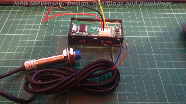
| John Stevenson | 16/11/2015 23:01:27 |
5068 forum posts 3 photos | Connected mine up today. Red on display connected to brown on sensor - both to 12v+ Black on display connected to blue on sensor - both to 12v- Yellow on display connected to black on sensor. Magnet stuck on cordless drill chuck, must have been lucky on which way as it all worked first time, no resistors or nothing. This is a blue display BTW. |
| Kevin Monks 1 | 22/02/2016 12:13:36 |
| 1 forum posts | Hi all, Quick Intro: Self-Employed welder/fabricator from Sunny Dorset. Like to do a bit of machining too. I own a Beaver model A milling machine, which I an in the process of re-assembling after 3 years of being in bits. Just a quick Thankyou for the information in this thread. I just bought the afformentioned rev counter (for my mill) at the begining of the thread and came across this during my google search for information to wire it up. All sorted now, no more head scratching. Cheers all. |
| Colin LLoyd | 08/11/2017 17:12:00 |
 211 forum posts 18 photos | I've got one of these to work with a 10mm dia x 10mm long high strength neodymium magnet (specification says these can lift 3.5kg) fitted to the spindle locking ring on top of the mill. As Howi says, even at 2500 rpm on my milling machine - the magnet doesn't move and I can have the sensor nearly 10 mm away from the magnet without loss of signal. But I suspect from a cursory look at the subject of the Hall Effect and general magnetic field effects that a strong narrow vertical magnet would provide better precision for the sensor response - in that the effect would be a quick "on-off" as apposed to the "rise & fall" that the wide magnet would give. And again - I'm guessing - at high RPMs, with the magnet width being a substantial part of the overall circumference, the sensor might not have returned to it's "Off" state before the next revolution brings the magnet into its sphere of influence. Perhaps someone with a better grasp of Hall effect proximity sensors than me could put me straight. |
| mtrehy mtrehy | 14/10/2018 17:33:42 |
| 22 forum posts 10 photos | HI, Would be very grateful for some help with this.... I have bought one of these and attached it to my bridgeport. It seems to behave very strangely. I have placed it on top and added a bit of hex bar at the end of the drawbar - hex is 30mm AF and I have attached the magnet on one of the corners of the hex so it's probably on a 35ish diameter.... The bridgeport has VFD. The rpm readout either jumps all over the place or doesn't read at all (----). It was slightly better but not perfect if I move the display a long way from the mill (I was suspecting some kind of interference). Doesn't make any difference whether the spindle is fast or slow. If I have the mill off and turn the spindle by hand it seems to read ok. If I try to replicate that speed with the slowest the mill will go it still plays up. Can the sensors and/or unit be affected by interference from the VFD? Apologies if this is a stupid question but it's not my area of expertise. Will the 30mm (approx) diameter of the magnet mounting be enough or does it need to be on a bigger disk? Any help greatly appreciated!
THanks
|
| Neil Wyatt | 14/10/2018 18:02:38 |
19226 forum posts 749 photos 86 articles | Have you tried reversing the magnet? A picture would help us understand your setup. Neil |
| Mike Poole | 14/10/2018 18:45:50 |
 3676 forum posts 82 photos | Is it possible the hexagon is behaving like a six weak poles? Try as an experiment putting it on a circular surface to eliminate the possibility. Mike |
| mtrehy mtrehy | 14/10/2018 18:48:30 |
| 22 forum posts 10 photos | I'll get some pics tomorrow. I tried magnet both ways and not a massive difference either way. Brass hex so I assume not possible to create any issue.... |
| Mike Poole | 14/10/2018 19:14:37 |
3676 forum posts 82 photos | Posted by mtrehy mtrehy on 14/10/2018 18:48:30:
I'll get some pics tomorrow. I tried magnet both ways and not a massive difference either way. Brass hex so I assume not possible to create any issue.... Oh well that shot that idea down in flames, to eliminate the VFC noise possibility could you lash it up on another machine with a conventional drive? Mike |
| mtrehy mtrehy | 17/10/2018 21:38:45 |
| 22 forum posts 10 photos | Managed to sort it out. Was definitely interference. Removed the sensor cable and twisted all 3 wires together, wrapped them in aluminium foil and then back in the sleeving and it now works perfectly. Thanks for all the replies.
|
| petro1head | 10/12/2019 13:51:37 |
 984 forum posts 207 photos | Sorry to resurect however I have just wired up one of these and this is the output. Somethings wrong - Video
|
| petro1head | 12/12/2019 10:49:26 |
984 forum posts 207 photos | Posted by petro1head on 10/12/2019 13:51:37:
Sorry to resurect however I have just wired up one of these and this is the output. Somethings wrong - Video
Sorted, I took a 10v supply from the VFD which was not a good idea. Now using a std 12v power supply and all is well |
| Mike Palmer 1 | 28/12/2020 16:41:47 |
| 32 forum posts 2 photos | This little bugger is driving me up the wall, I connected as diagram on back of display switched on and got display with numbers on and thought all is well, but when I ran the spindle no numbers just display showing zeros. Removed the sensor from machine and tried waving magnet across sensor but no joy. Played around different combination of connections but still no numbers. Reading the above posts there seems to be a question on pin 2, should it be connected to ground? I have tried this but to no effect. Anyone got thoughts! Thanks
Mike |
| JasonB | 28/12/2020 16:52:53 |
 25215 forum posts 3105 photos 1 articles | It's the negative of the power supply not Ground as in Earth. |
Please login to post a reply.
Magazine Locator
Want the latest issue of Model Engineer or Model Engineers' Workshop? Use our magazine locator links to find your nearest stockist!
Sign up to our Newsletter
Sign up to our newsletter and get a free digital issue.
You can unsubscribe at anytime. View our privacy policy at www.mortons.co.uk/privacy
Latest Forum Posts
- *Oct 2023: FORUM MIGRATION TIMELINE*
05/10/2023 07:57:11 - Making ER11 collet chuck
05/10/2023 07:56:24 - What did you do today? 2023
05/10/2023 07:25:01 - Orrery
05/10/2023 06:00:41 - Wera hand-tools
05/10/2023 05:47:07 - New member
05/10/2023 04:40:11 - Problems with external pot on at1 vfd
05/10/2023 00:06:32 - Drain plug
04/10/2023 23:36:17 - digi phase converter for 10 machines.....
04/10/2023 23:13:48 - Winter Storage Of Locomotives
04/10/2023 21:02:11 - More Latest Posts...
- View All Topics
Support Our Partners


Shopping Partners
Subscription Offer

Latest "For Sale" Ads
- Reeves** - Rebuilt Royal Scot by Martin Evans
by John Broughton
£300.00 - BRITANNIA 5" GAUGE James Perrier
by Jon Seabright 1
£2,500.00 - Drill Grinder - for restoration
by Nigel Graham 2
£0.00 - WARCO WM18 MILLING MACHINE
by Alex Chudley
£1,200.00 - MYFORD SUPER 7 LATHE
by Alex Chudley
£2,000.00 - More "For Sale" Ads...
Latest "Wanted" Ads
- D1-3 backplate
by Michael Horley
Price Not Specified - fixed steady for a Colchester bantam mark1 800
by George Jervis
Price Not Specified - lbsc pansy
by JACK SIDEBOTHAM
Price Not Specified - Pratt Burnerd multifit chuck key.
by Tim Riome
Price Not Specified - BANDSAW BLADE WELDER
by HUGH
Price Not Specified - More "Wanted" Ads...
Get In Touch!
Do you want to contact the Model Engineer and Model Engineers' Workshop team?
You can contact us by phone, mail or email about the magazines including becoming a contributor, submitting reader's letters or making queries about articles. You can also get in touch about this website, advertising or other general issues.
Click THIS LINK for full contact details.
For subscription issues please see THIS LINK.
Digital Back Issues


Donate

 Register
 Log-in
Model Engineer Magazine
- Percival Marshall
- M.E. History
- LittleLEC
- M.E. Clock

ME Workshop
- An Adcock
- & Shipley
- Horizontal
- Mill

Subscribe Now
- Great savings
- Delivered to your door

Pre-order your copy!
- Delivered to your doorstep!
- Free UK delivery!
All Forum Topics > Electronics in the Workshop > RPM Counter connections