Forum sponsored by:

The Workshop Progress thread 2018
| Meunier | 03/05/2018 21:55:43 |
| 448 forum posts 8 photos | Posted by John Haine on 02/05/2018 09:38:47:
Inspired by another thread, I got one of these 133 mm backplate castings from RDG...
My mind must have been wandering because I immediately jumped to the (wrong) conclusion and wondered how you were going to cut the 133 teeth on that.....hmmm |
| richardandtracy | 04/05/2018 04:38:31 |
 943 forum posts 10 photos | Posted by Jon Gibbs on 03/05/2018 10:41:29:
Posted by John Haine on 02/05/2018 22:52:13:
Why wouldn't a lathe one work? The geometry should be just the same whether the tool or the work rotates. +1, I use several cheap Chinese SCLCR boring bars with CCMT-06XXX inserts shortened and turned down to 3/8" in my boring head very successful... The banggood ones come with 10 inserts for around a tenner which is under the £15 import threshold if you can wait that long (2-3 weeks). HTH Jon Absolutely agree on this. If you start with the -S10 there's less to turn down and the holder's cheaper than the S12 too. Think I got my -S10 for under £4 last year, but without inserts (of which I already had enough) from cskwin2015 on E-Bay. Regards, Richard. |
| john feeney | 04/05/2018 09:49:44 |
 27 forum posts 37 photos | Thank you John & Joe, Thanks for the information. I`ll look into selecting a motor and a power supply. For my application I will often need to run for up to 30 mins so cooling may be a problem along with bearing life. Joe, in your set up how do you clamp the motors?, in all the small out runner motors ( IOO watts) I have used the outer case rotates along with the shaft. Perhaps I`m missing some thing simple ! John |
| Craig Booth 1 | 04/05/2018 13:00:20 |
| 84 forum posts 165 photos | I worked on my bench, new top and task lighting, whiteboard for scribbling on, and tool stand for commonly used bits.
|
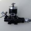
| Joseph Noci 1 | 04/05/2018 15:44:47 |
| 1323 forum posts 1431 photos |
Posted by john feeney on 04/05/2018 09:49:44: Thank you John & Joe, Thanks for the information. I`ll look into selecting a motor and a power supply. For my application I will often need to run for up to 30 mins so cooling may be a problem along with bearing life. Joe, in your set up how do you clamp the motors?, in all the small out runner motors ( IOO watts) I have used the outer case rotates along with the shaft. Perhaps I`m missing some thing simple ! John John, The motor has a face/flange that is normally fixed to the model plane's bulkhead/firewall, with the rotating motor body having the prop fixed to it at the non-flange end. The motor shaft normally protrudes from the rotating motor body at the end opposite to the mounting flange. That is not great, as the motor normally has a larger bearing at the flange end, and a smaller one at the 'prop' end we work like it opposite. What I do is remove the motor shaft altogether, and fit a long shaft ER series collet chuck, with the chuck at the flange end. Fix the flange to your machine mount, and all should be clear.. Some pics and explanations- The motor below right is 60mm diameter, has a 10mm shaft. The prop mount is fixed to the rotating motor body. The opposite end where the shaft protrudes is the mounting flange end - butts up against the mounting surface and screw hold the flange against said surface. The lower left and centre is a motor with the outer case and shaft pulled free of the windings - the left is a view of the motor mounting flange.
This is a smaller motor, again the left bottom view is the mounting flange end - the top view shows said flange at the left side.
And another motor - the one I use on my CNC router/engraver - Has 10mm shaft which I replaced with an ER collet. The flange is seen on the left
And the motor stripped: The mounting flange viewed end on at left view.
This is a view of the high speed sensitive drill I made - the aluminium body a bearing at the load end and the ER collet shaft goes through them, into the outer body of the motor ( replacing the original motor shaft) The motor mounting flange is seen screwed onto the aluminium body.
Heres a cross section, if it helps..
regards Joe |
| mechman48 | 05/05/2018 20:03:11 |
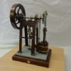
 2947 forum posts 468 photos | Stripped down my vertical cross engine; found that the location bosses top & bottom of cylinder covers were blocking the air/steam passages, the dwg says these should be 1.5 mm, had to machine back to 0.75mm to allow air to pass into cylinders... |
| JasonB | 05/05/2018 20:12:35 |
 25215 forum posts 3105 photos 1 articles | George you will find that if a small area of the spigot is milled away where the passage is you can get a good airflow and still keep the full spigot length.
|
| mechman48 | 06/05/2018 14:08:57 |
2947 forum posts 468 photos | Thanks for the tip Jason; will do that next time in the man cave, still need to sort out the spool valve methinks. |
| John Haine | 06/05/2018 22:47:12 |
| 5563 forum posts 322 photos | Posted by John Haine on 02/05/2018 09:38:47:
Inspired by another thread, I got one of these 133 mm backplate castings from RDG...
...and created a lot of cast iron dust to liberate this:
Used in anger for the first time today. Seems much more rigid, better finish, pleased! |
| Mark Rand | 06/05/2018 23:42:27 |
| 1505 forum posts 56 photos | Quick change Gibraltar toolpost |
| mechman48 | 11/05/2018 11:00:46 |
2947 forum posts 468 photos | Following Jason's tip I titivated both top & bottom cylinder covers, milling a small cutaway into the locating bosses. Having already machined back the bosses to 0.75mm. I didn't have much option but to leave it as is. It certainly improves the airflow to the cylinder but still have air passing the spool valve... definitely something wrong with spool valve, size, clearances, methinks making a new one is the solution... |
| Jim Nic | 11/05/2018 12:55:41 |
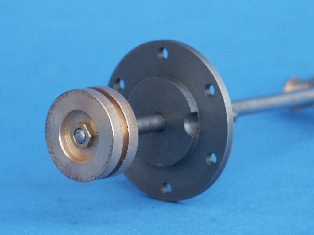
 406 forum posts 235 photos | George I'm a little puzzled by your having problems with the spool valve on your Vertical Cross engine as in my experience they are normally simple to make and reliable. I have a total of 5 such valves on 3 different engines, all have used 6mm silver steel rod as the basis for the valves working in a 6mm reamed bore. These from my Paddleduck are the most complex:
Good luck with the investigation, I hope whatever cure is required is not too drastic. Jim |
| mechman48 | 11/05/2018 14:53:49 |
2947 forum posts 468 photos | Thanks Jim.
|
| Jim Nic | 11/05/2018 16:17:58 |
406 forum posts 235 photos | George I've checked my retained drawings and have noted no "improvements" to Stew's design so all I can say without stripping the engine is that the valve is made to drawing. The valve chest is almost to drawing, the only changes are making it with a closed bottom end (rather than boring it all through and then plugging it) and putting the exhaust holes on the front face to facilitate a cover with an exhaust pipe. Where is the leaking air in your engine going? My valve may also leak but any air could only go down the exhaust pipe and I wouldn't know! (I'm now going to have to go and check, of course) Jim |
| mechman48 | 12/05/2018 10:22:30 |
2947 forum posts 468 photos | Jim |
| Jim Nic | 12/05/2018 12:35:02 |
406 forum posts 235 photos | George That's the same drawing as I used. I checked my engine last evening and there is no appreciable leakage past the valve at its operating pressure of less than 10 pounds per squinch. Just a couple of suggestions of possible causes for your problem could be: incorrect valve dimension, a less than good fit between valve and bore, or incorrect positioning/range of movement of the valve. Given that the valve is made to drawing how closely does it fit the bore? If that is satisfactory is the throw on the eccentric correct and is the valve rod the correct length and set to move the valve at the correct time in the crank cycle? Jim
|
| mechman48 | 12/05/2018 12:48:12 |
2947 forum posts 468 photos | Jim |
| JasonB | 13/05/2018 14:00:52 |
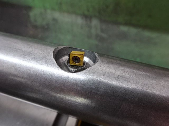
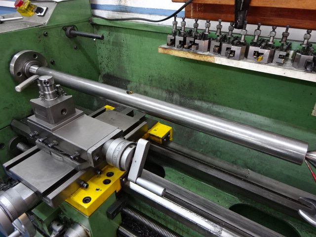
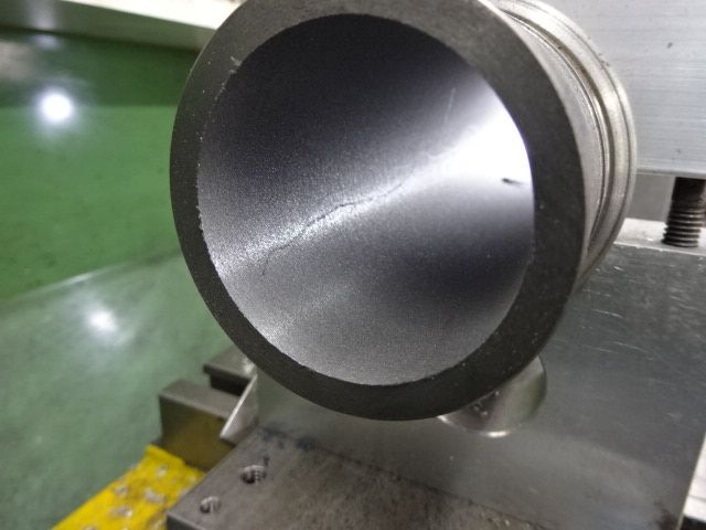
25215 forum posts 3105 photos 1 articles | I decided to do a bit on teh Otto Langen which has been sitting about waiting to have the 300mm long CI cylinder bored out to 42.8mm. I posted a while back the bar being turned to fit the lathe so the next job was to machine the hole for the Microbore insert to fit into which went without issue.
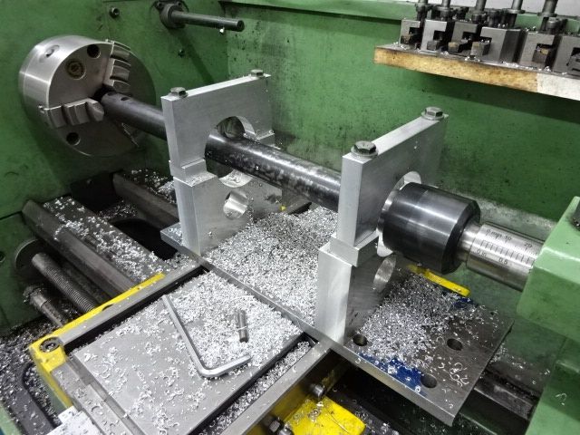
With the boring bar made there was no excuse not to make the cradle to hold the column so a few bits of steel and aluminium were cobbled together and bored out to fit the column.
With the small spacing blocks removed the column could be gripped and the boring bar slipped into position.
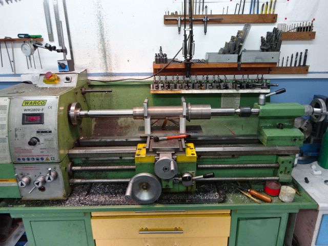
Then a few long boring cuts in both sense of the word. Not too bad a finish and no chatter which was good, will need a bit of honing and or lapping but that's easy enough. The wavy line is just where the vacuum cleaner nozzle rubbed.
|
| jimmy b | 13/05/2018 18:59:33 |
 857 forum posts 45 photos |
I was going to put flats on the drill chuck end, but figured that it'd just slip if there was any obstruction !
Jim |
| mechman48 | 15/05/2018 13:30:53 |
2947 forum posts 468 photos | Sun actually; Made a new spool valve, original was too short, + too much clearance 'tween the valve & bore. new valve seals off the ports better from what I can see & the valve is a neater fit in bore. Next noticeable fault... crank throw doesn't seem to be enough to allow full stroke of valve sequencing... methinks some numpty ( |


 .
.


This thread is closed.
Magazine Locator
Want the latest issue of Model Engineer or Model Engineers' Workshop? Use our magazine locator links to find your nearest stockist!
Sign up to our Newsletter
Sign up to our newsletter and get a free digital issue.
You can unsubscribe at anytime. View our privacy policy at www.mortons.co.uk/privacy
Latest Forum Posts
- *Oct 2023: FORUM MIGRATION TIMELINE*
05/10/2023 07:57:11 - Making ER11 collet chuck
05/10/2023 07:56:24 - What did you do today? 2023
05/10/2023 07:25:01 - Orrery
05/10/2023 06:00:41 - Wera hand-tools
05/10/2023 05:47:07 - New member
05/10/2023 04:40:11 - Problems with external pot on at1 vfd
05/10/2023 00:06:32 - Drain plug
04/10/2023 23:36:17 - digi phase converter for 10 machines.....
04/10/2023 23:13:48 - Winter Storage Of Locomotives
04/10/2023 21:02:11 - More Latest Posts...
- View All Topics
Support Our Partners


Shopping Partners
Subscription Offer

Latest "For Sale" Ads
- Reeves** - Rebuilt Royal Scot by Martin Evans
by John Broughton
£300.00 - BRITANNIA 5" GAUGE James Perrier
by Jon Seabright 1
£2,500.00 - Drill Grinder - for restoration
by Nigel Graham 2
£0.00 - WARCO WM18 MILLING MACHINE
by Alex Chudley
£1,200.00 - MYFORD SUPER 7 LATHE
by Alex Chudley
£2,000.00 - More "For Sale" Ads...
Latest "Wanted" Ads
- D1-3 backplate
by Michael Horley
Price Not Specified - fixed steady for a Colchester bantam mark1 800
by George Jervis
Price Not Specified - lbsc pansy
by JACK SIDEBOTHAM
Price Not Specified - Pratt Burnerd multifit chuck key.
by Tim Riome
Price Not Specified - BANDSAW BLADE WELDER
by HUGH
Price Not Specified - More "Wanted" Ads...
Get In Touch!
Do you want to contact the Model Engineer and Model Engineers' Workshop team?
You can contact us by phone, mail or email about the magazines including becoming a contributor, submitting reader's letters or making queries about articles. You can also get in touch about this website, advertising or other general issues.
Click THIS LINK for full contact details.
For subscription issues please see THIS LINK.
Digital Back Issues


Donate

 Register
 Log-in
Model Engineer Magazine
- Percival Marshall
- M.E. History
- LittleLEC
- M.E. Clock

ME Workshop
- An Adcock
- & Shipley
- Horizontal
- Mill

Subscribe Now
- Great savings
- Delivered to your door

Pre-order your copy!
- Delivered to your doorstep!
- Free UK delivery!
All Forum Topics > Work In Progress and completed items > The Workshop Progress thread 2018