Member postings for richardandtracy
Here is a list of all the postings richardandtracy has made in our forums. Click on a thread name to jump to the thread.
| Thread: Quick bolt Reserve Factor Calculator |
| 21/09/2020 14:52:36 |
Posted by ega on 20/09/2020 11:17:43:
Richard: Someone (whose name I don't remember) said that his life's ambition was to write a piece of software that would benefit others, and put it into the public domain. Not a bad aim in life. Always good to be able to offer up something useful by way of a thank-you for help received. Regards, Richard |
| 21/09/2020 14:49:47 |
In response to requests for smaller size threads, I have dug out data on M1.4 to M3.5 threads. If you have already downloaded the program, there is no need to do so again, just open BoltData.csv in Notepad or a suitable text editor and append the following data: M1.4 x 0.3,0.907 Then save the file as a UTF-8 text file (normal old-fashioned DOS text before extended character sets were invented). This will add the data for the smaller metric threads. In these small sizes I have specified the pitch because not all taps & dies conform to the 'ISO Coarse' thread standard pitch by default. The additional thread sizes are now included as standard in the download from my web site. Regards, Richard |
| 20/09/2020 10:25:05 |
I'm pleased it works for you, and it's nice to hear it works on Linux too. Regards, Richard. |
| 20/09/2020 07:12:17 |
Most of my usage has been M6-M16 but I have recently had cause to specify up to M63 for a little 6 tonne spacecraft turnover and transport trolley. Regards, Richard |
| 19/09/2020 22:24:18 |
This is a little 32 bit windows program to see what the reserve factors are in the heavily loaded bolts you're using are. It's a tool I knocked up to speed writing stress reports at work, but it's simple enough to use as a design what-if tool, and may have wider application, which is why it's available for download on my website. The program looks like this:
Program description page and download is available through the link. The program input is on the left, output on the right. The program uses a table of British/ISO metric screw thread sizes, also standard materials used in bolts (plain grade 4.6, high tensile 8.8, cap heads 10.9 and several types of stainless) and permits you to specify the loads in Newton's, acceleration/duty factors in gravities as well as design factors. The results then are presented in the right half of the window. A reserve factor factor of less than 1 is highlighted in red as this is bad. The pdf help file suggests the acceleration/duty factors that may be sensible to consider. The bolt loads used in the input can be calculated by hand or in the bolt loads calculator that may be downloaded from my website. The help file also shows the formulae used to calculate the reserve factors to verify for yourself that it's telling the truth. The program can screenshot itself to provide an entry for a report should you need to keep one on record. (You won't believe how much time this saves a stress engineer with a 300 page report to compile, typically it can take 45 minutes to type up bolt calculations, and double check each line in them. This is a single button press and then a paste. Imagine this saving 50 times in a report...) If you have materials not on the material list, or sizes not on the size list, both lists can be edited in accordance with the help file to add the new properties. The program is in metric. Only metric. I wrote the program for use at work in a modern engineering business. Imperial units have not been used there for 30 years. I am not going to risk breaking the program/ reducing simplicity for obsolete measurement units. Hope you find it useful. It has saved me hours since I wrote it earlier this year, and I wonder why I didn't do it years ago. I have had another stress engineer verify the output, so provided the input is correct, you can rely on the output. Regards, Richard. |
| Thread: Aluminium thread strength |
| 15/08/2018 08:23:48 |
With most metals the ratio of shear to tensile stress is in the range 65% to 70%. There are one or two oddities as low as 63% and some as high as 72% (According to the US document MIL-HDBK-5J [now obsolete as free standards become less obtainable]). The general figure used is 65% unless specific information is available. For a bolt in tension you should always use a stress area based on the minimum minor diameter if the thread as it's conservative. In shear, provided the bolt shank passes through the possible slip plane between two parts, the shank area may be used (which is larger) otherwise use the minor diameter based cross sectional area. When there is shear, the bolt shank may abut on the metalwork on either side. The area needed depends on the bearing/bruising stress of the base metal, which (again from a survey of MIL-HDBK-5J) is between 1.9 and 2.1x the tensile strength. I conservatively use 1.9x. This then gives a handle on how far the centroid of the abutment load acts from the slip plane. This in turn allows a calculation of any bending stress that may occur in the bolt during shear loads. All this depends on the conservative assumption that there is no pre-load on the bolts and therefore no friction to overcome, all of which make the joint stronger than calculated. Preload in the bolts is not additive to any tensile load unless you are going to analyse the joint to the nth degree. A reasonable working assumption is that as the joint is pulled apart, the pre-load at the joint is relaxed at a ratio of 1:1 while the bolt tension remains the same until the bolt pre-load is exceeded and the joint can gap. In practice the bolt tension goes up a little, the amount being dependant on a complex ratio between the bolt stiffness and joint stiffness. This is a reason why many cylinder head bolts are waisted, to make them stretch more, therefore see a lower load variation as the cylinder fires, and therefore have a higher fatigue life. Regards, Richard.
|
| 14/08/2018 22:00:03 |
It is a rough approximation, but mostly right most of the time. Must point out it's 2D with insert or 3D without = grade 8.8 bolt strength in 6082-T6 provided the area of the bar is enough. Would tend to go for bigger is better.. But sometimes lots of small bolts is better. Can't remember offhand the xsectional of an M6 (don't often use bolts smaller than M8 at work). We use 30.6mm^2 for an M8 as we use the minimum minor diameter for the stress area. Ideally the bar will be double the bolt diameter to ensure the normal load distribution within the thread, when less than 2D bar diameter a smaller length of thread seems to be worked harder. 10mm 6082 bar will have a strength of 295 N/mm^2 minimum, and yield of 255 when it starts stretching enough to be of interest. Hope this helps Regards, Richard.
|
| 14/08/2018 21:20:51 |
As a stress engineer as part of my daytime job... It's more down to the aluminium grade and if you are going to remove the thread often. More than 2-3 undoings in 6082T6 and you need an insert. About 2 D insert length is as strong as a grade 8.8 bolt. 3D (18mm) for a 12.9. For no insert, add 6mm (1D) to get the same strength. Much over 3D and not all the engaged thread works, just the first 3D. So, 3D insert for cap heads, or insert for many removals. Else no insert. In 6063, the aluminium is weaker, add 0.5D for engagement length, limit 3D again. For 2014/7075 almost don't need an insert. Regards, Richard.
|
| Thread: Kempes yearbook, worth getting? |
| 14/08/2018 20:58:07 |
I have the two volume 1988 version and refer to two pages almost daily at work (metric threads and minor diameters). I look at the rest every few months or so. I really don't need it for my workshop, which is why I keep it at work. So, if you can borrow a copy, I'd suggest that option before buying. Regards Richard. |
| Thread: Are Model Engineering Exhibitions The Same |
| 14/08/2018 15:11:16 |
Posted by RevStew on 14/08/2018 14:49:25:
I always think of the golf club dress code as a general benchmark...Not plus fours mind you... ... What?!? Next they'll be complaining about the deerstalker & shooting stick, doncherno. Regards, Richard.
|
| Thread: machine mart CL oil level sight glass |
| 14/08/2018 12:13:54 |
I have one but don't know the thread. I presume it's because you broke it? If it is because it's broken, take the bits out of the hole & measure the thread with a thread gauge, or measure the thread on any of the fragments you can get out. As a temporary measure, you could carefully drill & tap an acrylic sheet cover over the hole, seal with silicone, allow to cure & fill to the centreline with oil. This would enable you to use the lathe to make a replacement measured from the fragments. If you use acrylic bar to make the replacement, be aware that acrylic bar available in this country is usually extruded & has built-in stresses that make it crack (if not immediately, then eventually) when machined. You can anneal the acrylic by simmering in water on the stove top for 30 mins per inch in diameter and then allow to cool in the water off the stove. Once done, the acrylic won't crack. Alternatively buy clear cast acrylic bar (virtually unobtainable in the UK - I have looked for pen making). Regards, Richard.
Edited By richardandtracy on 14/08/2018 12:17:47 |
| Thread: Help to select and lay concrete reinforcing mesh |
| 14/08/2018 10:32:30 |
Posted by Speedy Builder5 on 14/08/2018 07:43:09:
BobH, in my situation it was not wrong. I made a hole in the ground the full size of the building footprint and the slab went under the walls, Being supported in the middle of the floor with minimum weight there and maximum weight at the edges will make my slab hog should there ever be sinkage due to the extra pressure from the walls, so the centre of the slab will be in tension. I did know what I was doing, I simply had not fully explained the situation because it was not relevant to the point I was making. I did not advocate putting the mesh near the top of the slab, just said that was what I did. When it came to the DPC, I lined the hole with it, then tucked it under the first layer of bricks when building the wall. Also put a further DPC 3 bricks up the outer skin of wall. When it comes down to it, in my case having a building with any form of slab will be better than what was there - and that lasted at least 100 years. In fact a number of the bricks that we re-used had paint inside the wall we dismantled, indicating those bricks are now in their third building at the very least. Regards, Richard.
|
| Thread: Which is better? |
| 14/08/2018 08:55:03 |
Posted by RevStew on 13/08/2018 21:11:08:
...I do like the Gingery lathe idea. I'd considered that a while ago, and I got the (I think it was the Sparey) book too. Part of the appeal is the crucible bit, even if only to make the neighbours think 'what dreadful alchemy, may I ...
The Gingery lathe is basic, but functional. Being basic, it forces you to be a better machinist if you are to get the same quality of work out of it that you'd get from a less basic machine. Takes longer, but you learn more. As for the furnace, I have made a similar one from available materials. Did it in 2002. and I wrote it up here: **LINK** . It is now on the point of having the base drop out (15 years on), but I have done 50 odd firings with it, and it cost £2 at the time. In the article I wrote I've also written about different fuels. At the moment I'm using 1" cube chunks cut from a hardwood conservatory a local builder gave us after he replaced it - we have a 'reputation' locally for taking any fuel people offer us. Pallets, timber, spare logs etc. If it's woodlike & flammable we'll take it to reduce our heating bills, and it saves them a tip trip. The hardwood chunks release much more heat than pallet timber, but quite a bit more slowly, so they need to be cut quite small to increase the surface area to release the heat fast enough. Anyway, once the furnace is hot enough with timber it consumes its own smoke, so is virtually smoke free and bothers the neighbours no more, and probably less, than a barbecue. Regards, Richard.
|
| 13/08/2018 22:15:00 |
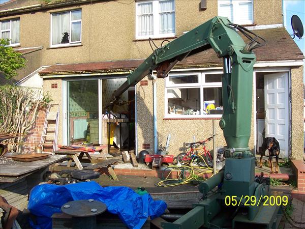
Posted by JasonB on 13/08/2018 20:54:45:
True, the Rev may live on his own in which case any room can be used for his hobby
Having difficulty seeing any problem in that photo. Looks like a useful setup. Shame there's a dog when a cat would be more sensible, otherwise it looks just tickety-boo to me. Regards, Richard.
|
| 13/08/2018 20:47:58 |
To whom? Presumably not the person who decided to put it there. Regards, Richard. |
| Thread: Help to select and lay concrete reinforcing mesh |
| 13/08/2018 20:46:18 |
Consider buying a sheet that's big enough. Quite a few sizes are available. For our 12x 13 ft building we got a sheet 14ft X 16 ft. Was available as a cut size from our local builder's merchant. Regards, Richard. |
| Thread: Which is better? |
| 13/08/2018 20:40:56 |
I think that possibly your magazine does not exist. The closest to it may be MEW, but it's obviously not a perfect fit. LBSC was a wonderful author. Nothing seems impossible under his guidance, and I think his whole can-do attitude got everyone else talking in the same vein. Right. You don't have the money for your hobby. There are two solutions. Find more money by hook or by crook, or do something radical. I assume the money side is intractable, and if you are a 'Rev' by profession, it will be, so can I suggest something radical? Make your own machine shop. Be your own industrial revolution. Sounds unlikely, but hear me out. In the 1980's there was an American called David Gingery who was faced with the same problem as you. Difference being he knew his stuff and was able to apply his engineering knowledge to solving the problem, and also wrote a series of books about it to teach other how to do the same, his 'Make a Machine Shop from scrap' series. These books start you off with nothing but a few basic hand tools and end you up with a well equipped workshop. How? Book 1 makes a charcoal crucible furnace using hand tools Book 2 uses the hand tools and furnace to make a 7" swing lathe. Book 3 uses hand tools, the furnace and lathe to make a 7" metal shaper. Book 4 uses hand tools, the furnace, lathe and shaper to make a milling machine. Book 5 uses hand tools, the furnace, lathe, shaper and mill to make a drill press Book 6 uses everything to make a dividing head, 4 jaw chuck etc. There are only aluminium castings and bits of cold rolled steel used in making the machines. Everything is shown and all necessary techniques learnt as you go along. I am a professional mechanical engineer, and would be proud to have designed or made any of the machines featured. They are a perfect fit for someone who simply cannot scratch the money together for a commercial machine. The books are available at Camden Miniature Steam Services. Hmm. Not considering 3D printing as 'Engineering'. I have to disagree with you on that. There is no traditional engineering, if you think that engineering is limited to the manufacturing phase of the build. If you think that, then I fear you are mistaken. As things become more 'engineered' the engineering input is concentrated in the design phase. In the case of 3D prints, the engineering can only be in the design phase. If the material properties, strength, shape and overall form are properly considered, then the design phase is all engineering. If, however, the design is just knocked together in a few seconds by someone using a printer for the first time, then there is probably no engineering input at all. Regards Richard
|
| Thread: Facing Error |
| 13/08/2018 13:34:14 |
SoD, I really don't think that last measurement of yours is meaningful. As the cross slide goes past the DTI, all you have discovered is the flatness of an unimportant face on your cross slide. Imagine if there were corrugations on that rear face you've just measured, how would it affect the machining of the tool tip? Frankly, not one iota. It does show, though, that actually you have a nicely made machine. It is of interest, but of no consequence to the possible squareness or not of the cut. Regards, Richard.
|
| Thread: Which books |
| 12/08/2018 22:09:39 |
Think that at the moment home CNC is in a pretty immature state compared to other branches of the hobby, and is changing rapidly enough to date very quickly. Think of the advent in the last couple of years of the little self contained controllers, the Arduino and the PlanetCNC type controllers all changing so rapidly that a book would become out of date while being written. The same applies to 3D printing, only more so. Regards, Richard. |
| Thread: What did you do Today 2018 |
| 12/08/2018 21:34:06 |
Andrew, given the machining time, I'd be tempted to do a run with acrylic rather than aluminium - just reduces the chance of cutter breakage further. I managed to take an hour to cut a 10mm dia pen cap decal with a 0.3mm dia cutter in acrylic, and it didn't break. Regards Richard. |
Magazine Locator
Want the latest issue of Model Engineer or Model Engineers' Workshop? Use our magazine locator links to find your nearest stockist!
Sign up to our Newsletter
Sign up to our newsletter and get a free digital issue.
You can unsubscribe at anytime. View our privacy policy at www.mortons.co.uk/privacy
Latest Forum Posts
- *Oct 2023: FORUM MIGRATION TIMELINE*
05/10/2023 07:57:11 - Making ER11 collet chuck
05/10/2023 07:56:24 - What did you do today? 2023
05/10/2023 07:25:01 - Orrery
05/10/2023 06:00:41 - Wera hand-tools
05/10/2023 05:47:07 - New member
05/10/2023 04:40:11 - Problems with external pot on at1 vfd
05/10/2023 00:06:32 - Drain plug
04/10/2023 23:36:17 - digi phase converter for 10 machines.....
04/10/2023 23:13:48 - Winter Storage Of Locomotives
04/10/2023 21:02:11 - More Latest Posts...
- View All Topics
Support Our Partners


Shopping Partners
Subscription Offer

Latest "For Sale" Ads
- Reeves** - Rebuilt Royal Scot by Martin Evans
by John Broughton
£300.00 - BRITANNIA 5" GAUGE James Perrier
by Jon Seabright 1
£2,500.00 - Drill Grinder - for restoration
by Nigel Graham 2
£0.00 - WARCO WM18 MILLING MACHINE
by Alex Chudley
£1,200.00 - MYFORD SUPER 7 LATHE
by Alex Chudley
£2,000.00 - More "For Sale" Ads...
Latest "Wanted" Ads
- D1-3 backplate
by Michael Horley
Price Not Specified - fixed steady for a Colchester bantam mark1 800
by George Jervis
Price Not Specified - lbsc pansy
by JACK SIDEBOTHAM
Price Not Specified - Pratt Burnerd multifit chuck key.
by Tim Riome
Price Not Specified - BANDSAW BLADE WELDER
by HUGH
Price Not Specified - More "Wanted" Ads...
Get In Touch!
Do you want to contact the Model Engineer and Model Engineers' Workshop team?
You can contact us by phone, mail or email about the magazines including becoming a contributor, submitting reader's letters or making queries about articles. You can also get in touch about this website, advertising or other general issues.
Click THIS LINK for full contact details.
For subscription issues please see THIS LINK.
Digital Back Issues


Donate

 Register
 Log-in
Model Engineer Magazine
- Percival Marshall
- M.E. History
- LittleLEC
- M.E. Clock

ME Workshop
- An Adcock
- & Shipley
- Horizontal
- Mill

Subscribe Now
- Great savings
- Delivered to your door

Pre-order your copy!
- Delivered to your doorstep!
- Free UK delivery!