Forum sponsored by:

WARCO WM-250 lathe family and WM16 mill - 001
........advice and support for owners.
| Rik Shaw | 10/03/2014 20:10:12 |
 1494 forum posts 403 photos | Hello Ron Don't know whether you have read all the posts on this thread re: WM16 but I would say that they cover a fair range of things to look out for especially when installing DRO's. You are going to be drilling machine castings to get your scales fitted - just hope yours are softer than mine were! Rik |
| mechman48 | 11/03/2014 11:09:57 |
 2947 forum posts 468 photos | Hi Ron Look in my album; I have fitted X & Y axis DRO's to my WM 16 without too much bother, having fitted the X axis to the front I have removed the ability to have the table stops useable, but this can be remedied by extending the fastenings further out if need be, so far it's no big loss. Some have fitted the X DRO to the rear of the table.. personal choice. George. |
| Ron Vale | 11/03/2014 18:30:53 |
| 24 forum posts | Mechman
Thanks for the heads up re fitting. Would i be correct in saying that to fit the y DR you only need to remove the end ' end wheel' and associated mountings?
Ron |
| mechman48 | 11/03/2014 19:13:48 |
2947 forum posts 468 photos | Hi Ron Yes, you only need to remove the hand wheel & end casting ( make sure you have the table fully extended as far as poss' ) to allow you easier access for drilling the mounting holes & to ensure that you level up & align the scale & reading head. Whilst I had mine adrift it gave me the chance to inspect the leadscrew thrust bearing & clean ,relube' before reassembly, also it gave me the opportunity to scrape off paint that had over sprayed on the joint prior to factory assembly as I had noticed that there was a slight drip from the joint when I was using coolant at one stage so I scraped the joint clean, fitted a brown paper gasket ( lightly greased ).. in fact I did both ends whilst in the process.. sorted. George |
| Ron Vale | 13/03/2014 11:36:15 |
| 24 forum posts | George, As they say a picture is worth a thousand words.Just what i needed
I am going to get a 200mm DRO for the Y axis and a 600mm for the X Do you think that they will be adequate.? Was considering a 500mm for the X but as the travel is 485mm thought it might be a bit 'tight'
Ron |
| john kennedy 1 | 16/03/2014 17:18:53 |
 214 forum posts 24 photos |
Got my new inverter and 3 phase motor fitted in the wm250. The motor is much bigger than the dc one it was replacing.
Didn't fancy hanging this lump off the back of the headstock. A bit of work with the angle grinder allowed me to fit it in a swinging cradle underneath. (you'll notice i forgot to thread the gland nut on one of the cables
Its all running ok now but was a bit of a game (for me) working out how to set it up using the lathes switch and speed pot. Must say I'm quite proud of myself
The slowest pulley ratio I could get (not having a working lathe to make some) is 540 rpm. The picture shows it running at 20 hz, which in theory is 108 rpm. The next picture shows it turning 100mm dia steel with 1mm deep cut at 20hz. and the motor is as cool as a cucumber... I've got an electric fan for it which I will wire up on a seperate switch. Got to say this is so much better with loads of torque for doing the odd large dia job. Was thinking of later making an intermediate twin pulley to halve the 50 hz speed to 270 rpm If your dc motor is struggling,change over,you wont regret it..... |
| Les Jones 1 | 16/03/2014 18:09:36 |
| 2292 forum posts 159 photos | Hi John, Les. |
| john kennedy 1 | 16/03/2014 18:29:05 |
214 forum posts 24 photos | Thanks Les but this version doesn't have a tumbler as such. On the front of the lathe you will see 2 knobs,one is to reverse the leadscrew and the other can be switched to 3 positions to give 3 speeds with the given geartrain . John |
| Les Jones 1 | 16/03/2014 18:47:51 |
| 2292 forum posts 159 photos | Hi John, Les. Edited By Les Jones 1 on 16/03/2014 18:50:49 |
| john kennedy 1 | 17/03/2014 06:15:07 |
214 forum posts 24 photos | That would be a nice project to publish. I bet there's loads out there struggling without it.John |
| Ed Duffner | 14/04/2014 17:18:53 |
| 863 forum posts 104 photos | Hi Everyone, A question for WM-16 or similar owners if I may. Have you tried fly-cutting mild steel (EN3B) and how did you get on? I've had a go with a standard type fly cutter (2MT) with both HSS and brazed carbide LH cutting tool and I just seem to blunt the bits and the material starts to burnish. I believe I've set the tool geometry correctly on the HSS bit and have tried speeds ranging from about 400RPM to 800RPM or so. Depth of cut was never greater than 0.2mm and slow, steady hand feeding as I don't have an auto-feed yet. Everything that needed to be locked down was done so. Thanks, |
| JasonB | 14/04/2014 17:31:15 |
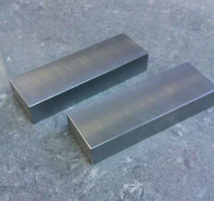
 25215 forum posts 3105 photos 1 articles | I have a similar sized X3 and get a reasonable finish from the flycutter. Nothing special just a cheapie set of 3 with 1/2" shanks, 1/4" HSS but run at what revs seem right. Not the crispest of photos but thats 1" x 1/2" mild steel cut down to 7/16". Hand fed with a dab of soluable oil applied with a brush.
Edited By JasonB on 14/04/2014 17:31:47 |
| Rik Shaw | 14/04/2014 17:53:51 |
1494 forum posts 403 photos | Ed - I fly cut regularly on one of these machines and get nice finishes mostly using HSS. You do have to practise with getting the tool ground correctly though. When you have it right the the tool bit hisses as it cuts and leaves a lovely finish. It's hard to give any further advice without seeing how you have ground your bit which of course, is not possible unless you live near me. Rik |
| Ed Duffner | 14/04/2014 17:59:28 |
| 863 forum posts 104 photos | Ok, thank you for the replies chaps. I'll have another go after I finish my cuppa. |
| Neil Wyatt | 14/04/2014 18:23:38 |
 19226 forum posts 749 photos 86 articles | 400-800 rpm seems very high for a fly cutter, unless it is a very small radius. In theory the 108rpm for a 100mm blank in the picture above can be turned on its head - 108 rpm for a fly cutter with radius 100/2=50mm. I run a ~ 35mm radius fly cutter at about 120rpm. Neil |
| Ed Duffner | 14/04/2014 21:15:37 |
| 863 forum posts 104 photos | I had another go and it seems to have improved. I find it a bit difficult grinding an even radius on HSS but think I have it now. I also just looked at my copy of Peter Wright's Model Engineering Foundation Course (comparing his photo of a cutting tool) and I have not included enough clearance angle for the edge that rubs against the cut face, so I was basically cutting a slight chamfer and the bit was trying ride up over the cut originally. Also in the book, it has a table for speeds but the printer has pushed text out of line and it's a bit unclear as to what the speed for BMS is. I just tried 250RPM but that felt way too slow. Then found 525RPM to be ok and I also reduced the amount of tool bit protruding from the cutter. Here are some photos. This as a piece of mild steel about 5/8" x ~4.5"
Edited By Ed Duffner on 14/04/2014 21:17:52 |
| Neil Wyatt | 24/04/2014 21:42:23 |
19226 forum posts 749 photos 86 articles | Hi Ed, In Peter Wright's table BMS should be one of the first 'group' with copper, gunmetal etc. Fly cutting is REALLY slow. I'm talking paint drying slow. I'm guessing from the marks that your cutter has a diameter of about 2". I'm amazed you haven't simply burnt the end of the cutter off. If you have the patience ry running at about 100 rpm and turn the handwheel really slow so it advances a few thou between cuts. You should then start getting the silky 'flycut' finish you want. If it feels too slow, you're feeding too fast. Of course, YMMV, but I'd be interested what speeds other use with what size of flycutter. Neil |
| Neil Wyatt | 25/04/2014 10:13:14 |
19226 forum posts 749 photos 86 articles | Hi John, Ouch! Wouldn't do that on an X2! I'd agree that the tool has to be right, a knife tool with a small tip radius will work if you're just taking off a light skim, but you won't get the surface finish. My workshop is in the middle of a major reorganisation, but I'll see if I can get a shot to the results I get. These days I usually use a 11.5mm slot drill with the corners ground off for facing. It leaves a 'swirled finish' but the result is smooth to the touch. I'm not sure I've used a flycutter since doing all the rigidity improvements to my mill. Neil |
| Mark P. | 25/04/2014 20:27:33 |
 634 forum posts 9 photos | Whilst on the subject of milling, has anyone converted their WM16 to inverter drive? The reason being I am contemplating doing this to mine ( I find that my motor eats brushes). Also is it the spindle gears which are plastic and will the ones Arceurotrade sell fit? When I do carry out this conversion I would like to retain the Hi Lo gears to increase the usable speed range. Regards Mark P. |
| Wolfgang Schulze-Zachau | 12/05/2014 22:25:26 |
| 8 forum posts | Hello everyone here! I have read this thread with a lot of interest. I am the owner of a 5 month old WM250VF with a milling attachment (my workshop is very small and there is no space for a separate milling machine). So far the lathe has done a very good job, after I went through some of the same exercises as most other posters here (tailstock alignment, back-plate facing off, etc.). Last night I ran into some trouble, though. Whilst parting off a piece of 20mm MS, the lathe jammed completely. It just stopped, and I switched it off immediately. After removing the tool and checking that the headstock moved freely (which it does). I tried switching it back on and...NOTHING. The main switch kicks in (soft clunk sound) and the display comes alive, but the motor doesn't run and the dsiplay shows 0. Has anybody had this before? I have emailed Warco and am currently waiting for their reply, but just wanted to hear whether I just need to reset some switch somewhere or check for something obvious. Any pointers would be highly appreciated. Wolfgang |


Please login to post a reply.
Magazine Locator
Want the latest issue of Model Engineer or Model Engineers' Workshop? Use our magazine locator links to find your nearest stockist!
Sign up to our Newsletter
Sign up to our newsletter and get a free digital issue.
You can unsubscribe at anytime. View our privacy policy at www.mortons.co.uk/privacy
Latest Forum Posts
- *Oct 2023: FORUM MIGRATION TIMELINE*
05/10/2023 07:57:11 - Making ER11 collet chuck
05/10/2023 07:56:24 - What did you do today? 2023
05/10/2023 07:25:01 - Orrery
05/10/2023 06:00:41 - Wera hand-tools
05/10/2023 05:47:07 - New member
05/10/2023 04:40:11 - Problems with external pot on at1 vfd
05/10/2023 00:06:32 - Drain plug
04/10/2023 23:36:17 - digi phase converter for 10 machines.....
04/10/2023 23:13:48 - Winter Storage Of Locomotives
04/10/2023 21:02:11 - More Latest Posts...
- View All Topics
Support Our Partners


Shopping Partners
Subscription Offer

Latest "For Sale" Ads
- Reeves** - Rebuilt Royal Scot by Martin Evans
by John Broughton
£300.00 - BRITANNIA 5" GAUGE James Perrier
by Jon Seabright 1
£2,500.00 - Drill Grinder - for restoration
by Nigel Graham 2
£0.00 - WARCO WM18 MILLING MACHINE
by Alex Chudley
£1,200.00 - MYFORD SUPER 7 LATHE
by Alex Chudley
£2,000.00 - More "For Sale" Ads...
Latest "Wanted" Ads
- D1-3 backplate
by Michael Horley
Price Not Specified - fixed steady for a Colchester bantam mark1 800
by George Jervis
Price Not Specified - lbsc pansy
by JACK SIDEBOTHAM
Price Not Specified - Pratt Burnerd multifit chuck key.
by Tim Riome
Price Not Specified - BANDSAW BLADE WELDER
by HUGH
Price Not Specified - More "Wanted" Ads...
Get In Touch!
Do you want to contact the Model Engineer and Model Engineers' Workshop team?
You can contact us by phone, mail or email about the magazines including becoming a contributor, submitting reader's letters or making queries about articles. You can also get in touch about this website, advertising or other general issues.
Click THIS LINK for full contact details.
For subscription issues please see THIS LINK.
Digital Back Issues


Donate

 Register
 Log-in
Model Engineer Magazine
- Percival Marshall
- M.E. History
- LittleLEC
- M.E. Clock

ME Workshop
- An Adcock
- & Shipley
- Horizontal
- Mill

Subscribe Now
- Great savings
- Delivered to your door

Pre-order your copy!
- Delivered to your doorstep!
- Free UK delivery!
All Forum Topics > Workshop Tools and Tooling > WARCO WM-250 lathe family and WM16 mill - 001