Forum sponsored by:

3 -Phase Conversion of a Mini-Lathe
A new online article
Articles
3-Phase Conversion and Other Alternative Methods of Powering a Mini-Lathe
After much experimentation with different ways of powering my mini-lathe on a keep it going basis, I finally decided to go the whole hog and install an inverter and 3-phase motor – to give me variable frequency drive. This is the whole story.
| Neil Wyatt | 02/07/2014 12:55:09 |
 19226 forum posts 749 photos 86 articles | Following my postings on my 3-phase conversion of my mini-lathe I got a few requests to publish an article on it in MEW. With articles by other authors 'queuing up' for publication, and this being rather an involved topic, I thought it would be fairer to post it as an online article. Please bear in mind the warnings in the article - only carry out work like this of you are competent to do so. I hope this proves of value to others. Neil |
| Michael Gilligan | 02/07/2014 14:14:14 |
 23121 forum posts 1360 photos | Thanks, Neil A useful reference. MichaelG. |
| Neil Wyatt | 03/07/2014 10:51:10 |
19226 forum posts 749 photos 86 articles | A much shorter article up today: http://www.model-engineer.co.uk/news/article/nicholson-the-guide-to-files-and-filing Thanks to Oompa Loompa for pointing me towards a very interesting public domain library. Neil Edited By Neil Wyatt on 03/07/2014 15:19:28 |
| blowlamp | 03/07/2014 13:59:50 |
 1885 forum posts 111 photos | Posted by Neil Wyatt on 03/07/2014 10:51:10:
A much shorter article up today: http://www.model-engineer.co.uk/news/article/nicholson-the-guide-to-files-and-filing Thanks to Oompa Loompa for pointing me towards a very interesting public domain library. Neil The link doesn't work for me.
Martin. Edited By Neil Wyatt on 03/07/2014 15:20:56 |
| Ian S C | 03/07/2014 14:29:53 |
 7468 forum posts 230 photos | Doesn't work here either. Ian S C |
| Neil Wyatt | 03/07/2014 15:20:38 |
19226 forum posts 749 photos 86 articles | Sorry both, for some reason the article number got lost from the end of the link. It should work now. I've fixed it in Martin's post as well. Neil |
| I.M. OUTAHERE | 19/11/2018 17:55:06 |
| 1468 forum posts 3 photos |
Old Thread i know ( sorry !) but as i’m doing a similar conversion or more of a modification to the current set up to my mini lathe i thought i would ask a few questions . The origional conversion i did still used the two speed gearing but recently i have started using this lathe more often the steel gears i fitted are whining thier teeth off and it is driving me insane ! I could use the majority of the set up i had but just use a longer belt to feed drive from the layshaft up to the spindle , this way i coud use a stepped pulley on the motor and layshaft to give either 1:1 or possibly 3:1 drive ratios but changing these over might be a fidget . I can also do the same as Neil has and run straight from motor to spindle with no reduction . Motor is 0.75 kw @ (i think ) 1380 rpm . Neil, now that this conversion has been in place for a few years how have you found the performance of the drive ratio you have now ? Do you feel it has impacted on low speed turning ? And if you had to do the conversion over again would you change anything ? One thing i really hate is the tumbler gear lever at the back so may change that also . Ian. |
| Neil Wyatt | 19/11/2018 18:12:23 |
19226 forum posts 749 photos 86 articles | I fitted a double-ended pulley to the motor, by switching it end to end I can have a higher speed range. Normally I use the 190mm end for best low-speed performance. Other than the original testing I have used the high speed range exactly zero times. Neil |
| Neil Wyatt | 19/11/2018 18:13:43 |
19226 forum posts 749 photos 86 articles | I also added a lever to adjust the banjo, with a belleville washer and extended nut for adjusting the tension. Works as a clutch and is brilliant. |
| I.M. OUTAHERE | 19/11/2018 18:38:27 |
| 1468 forum posts 3 photos | Thanks for your quick response Neil ! 190 mm pulley ? Is that meant to be 90 mm ? So you use the lever to lift the motor up and loosen the belt and leave the motor running ? I would also like a feature like that !
|
| I.M. OUTAHERE | 06/12/2018 05:12:55 |
| 1468 forum posts 3 photos | Just a quick update as to the progress of my conversion so others can use the info if they wish . My lathe has a previously fitted taper bearing conversion so some of the parts can be reused , i have now added grease nipples and grease ports to lubricate the bearings if wish . The alloy bearing covers have double lip seals fitted so the grease can only exit through the bearing and to the inside of the headstock . The pulley and belt were purchased , they were cheap enough to not bother making the pulleys which are steel and come with a 10mm pilot hole . The 4mm key slot on the spindle for the back gear has been lengthened so it picks up the pulley bore and the collar that the seal rides on was made for the previous conversion and just needed shortening . The alloy cover that the banjo fixes to will have two slots cut into it to allow the belt to exit to the rear of the headstock and this will run around the same size pulley that is on the spindle , this pulley will have transmission power fed to it via a set of "A" section V pulleys to allow a ratio change . I still have to finish the layout of those pulleys as i want a clutch which can be activated by pulling a lever to loosen the drive belt , i did briefly consider modifying a manual clutch from one of those cheap minibikes on ebay but i think it may be more work than what it is worth - still undecided . I will also be doing something with the tumbler gear set up as having the lever at the back is a pia , i might make a linkage system up so i can mount the positioning lever ontop of the headstock . If Neil doesn't mind i will keep posting in this thread , I didn't want to start a new thread to post the occasional update. Ian.
|
| Michael Gilligan | 06/12/2018 08:43:47 |
23121 forum posts 1360 photos | Looking good MichaelG. |
| John Haine | 06/12/2018 09:59:16 |
| 5563 forum posts 322 photos | If you have a VFD, do you need a clutch? |
| I.M. OUTAHERE | 06/12/2018 11:44:07 |
| 1468 forum posts 3 photos | Strictly speaking - no but they do make some operations easier and faster like power tapping / threading with a die . It also makes operations where you have to stop and measure frequently a bit easier and faster as you don't have to wait for the electronics to react to your input or for the motor to stop and start ,i know i can use the brake function to stop the chuck dead and use no or very little ramp up but I don't like such abrupt operations as it is hard on the driveline . It still remains to be seen if the friction or drag in the drivetrain will be enough to overcome the the drag from a loosened belt or open clutch and be enough to stop the spindle from turning while the motor is running but the benefit of being able to slip a clutch while power tapping makes the idea more attractive to me anyhow . I still have to make a mechanism to loosen the belt to change ratios and this would incorporate a lever and cam of some sort so that may be something that i can kill two birds with one stone with . Ian. |
| John Haine | 06/12/2018 14:50:36 |
| 5563 forum posts 322 photos | But I was thinking it doesn't have to be that abrupt. You can program the inverter to take say 3 seconds to ramp up or down, which is as fast as a clutch probably. On belt changing, depending on the belt you use - on my recent Unimat conversion I use a round belt with no provision to loosen it. They pulleys are designed so they always use the same length irrespective of ratio and its easy to shift from one to another by hand. I habitually power tap using the VFD on my mill. I line up the tap with the hole and hold it with the manual quill feed so the tap is just in the hole and pressing lightly. VFD is set to 6 - 10 Hz, I flick the fwd switch and cut until the thread is well established; then stop, let the mill stop (which it does very fast from such a low speed) then reverse it. If the hole isn't blind and there's a clear run on the other side I tap right through in one go; otherwise discretion is the better part of valour so I finish the thread by hand once the tap is running true. I have never broken even a small tap this way, though once I forgot to turn the speed down after drilling - that was exciting! I'm sure the same would work on the lathe. |
| I.M. OUTAHERE | 06/12/2018 16:12:20 |
| 1468 forum posts 3 photos | I'm using "A" section V belts so i will have to loosen to change the belt from one pulley to the next as there is no stretch in these belts , I'm using them because they are readily available from many suppliers , cheap, reliable and so are the pulleys . Iused the multi v belt on the spindle because of its low profile otherwise i would have to hack away most of the alloy cover that the banjo fits to . I could use the inching function on the vfd for tapping also . |
| I.M. OUTAHERE | 07/12/2018 05:22:15 |
| 1468 forum posts 3 photos | Today i completed the modifications to the alloy housing to allow the belt to feed through to the pulley , i also relieved the inside of the housing a little so the pulley face has some clearance and i then opened up the hole for the spindle about 3mm in dia . The cup shaped item on the end of the spindle is for the tacho proximity sensor
|
| I.M. OUTAHERE | 16/12/2018 06:20:09 |
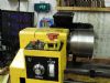
| 1468 forum posts 3 photos | Here is the motor sled and pulley set up (i have named it "The tower of power " ) it is made i little more heavy duty than what was needed because i used materials i had laying around but on the other hand it doesn't flex ! The jacking bolt on the front jacks the sled back to tighten the poly v belt , the motor bracket is hinged to adjust the v belt and this will also give me a clutch . The motor pulleys are 1-1/2 & 2-1/2 inch and the layshaft pulleys are 4 & 2 inch . The 1-1/2 & 4 inch give a reduction of 2.6:1 and the 2-1/2 & 2 inch are set up as an overdrive of 1:1.25 and with a motor speed of 1380 rpm low gear will yield approximately 530 rpm and high gear 1725 rpm - this is without overdriving the motor via the vfd .
|
| Michael Gilligan | 16/12/2018 08:35:22 |
23121 forum posts 1360 photos | A very tidy installation ... although I would prefer to see screwed fasteners used for motor mounting MichaelG. |
| I.M. OUTAHERE | 16/12/2018 09:57:17 |
| 1468 forum posts 3 photos | So do i but buggered if i could find where they were hiding |


Please login to post a reply.
Magazine Locator
Want the latest issue of Model Engineer or Model Engineers' Workshop? Use our magazine locator links to find your nearest stockist!
Sign up to our Newsletter
Sign up to our newsletter and get a free digital issue.
You can unsubscribe at anytime. View our privacy policy at www.mortons.co.uk/privacy
Latest Forum Posts
- *Oct 2023: FORUM MIGRATION TIMELINE*
05/10/2023 07:57:11 - Making ER11 collet chuck
05/10/2023 07:56:24 - What did you do today? 2023
05/10/2023 07:25:01 - Orrery
05/10/2023 06:00:41 - Wera hand-tools
05/10/2023 05:47:07 - New member
05/10/2023 04:40:11 - Problems with external pot on at1 vfd
05/10/2023 00:06:32 - Drain plug
04/10/2023 23:36:17 - digi phase converter for 10 machines.....
04/10/2023 23:13:48 - Winter Storage Of Locomotives
04/10/2023 21:02:11 - More Latest Posts...
- View All Topics
Support Our Partners


Shopping Partners
Subscription Offer

Latest "For Sale" Ads
- Reeves** - Rebuilt Royal Scot by Martin Evans
by John Broughton
£300.00 - BRITANNIA 5" GAUGE James Perrier
by Jon Seabright 1
£2,500.00 - Drill Grinder - for restoration
by Nigel Graham 2
£0.00 - WARCO WM18 MILLING MACHINE
by Alex Chudley
£1,200.00 - MYFORD SUPER 7 LATHE
by Alex Chudley
£2,000.00 - More "For Sale" Ads...
Latest "Wanted" Ads
- D1-3 backplate
by Michael Horley
Price Not Specified - fixed steady for a Colchester bantam mark1 800
by George Jervis
Price Not Specified - lbsc pansy
by JACK SIDEBOTHAM
Price Not Specified - Pratt Burnerd multifit chuck key.
by Tim Riome
Price Not Specified - BANDSAW BLADE WELDER
by HUGH
Price Not Specified - More "Wanted" Ads...
Get In Touch!
Do you want to contact the Model Engineer and Model Engineers' Workshop team?
You can contact us by phone, mail or email about the magazines including becoming a contributor, submitting reader's letters or making queries about articles. You can also get in touch about this website, advertising or other general issues.
Click THIS LINK for full contact details.
For subscription issues please see THIS LINK.
Digital Back Issues


Donate

 Register
 Log-in
Model Engineer Magazine
- Percival Marshall
- M.E. History
- LittleLEC
- M.E. Clock

ME Workshop
- An Adcock
- & Shipley
- Horizontal
- Mill

Subscribe Now
- Great savings
- Delivered to your door

Pre-order your copy!
- Delivered to your doorstep!
- Free UK delivery!
All Forum Topics > Workshop Tools and Tooling > 3 -Phase Conversion of a Mini-Lathe