Forum sponsored by:

Stuart 'No.1' : a beginners tale..
| GarryC | 09/04/2014 13:14:37 |
 740 forum posts 1043 photos | Back again I'm afraid, this time to have a go at my second project - a Stuart No.1 Steam Engine - following completion of the Stuart 'Victoria', which I enjoyed immensely. I believe the 'No.1' was the first model built and sold by Mr Stuart Turner over 110 years ago, sometime during the 1890's - which appeals to my sense of history and add's something for me to the project. It's a fair sized and heavy model and when on a small base should stand about 15 inches high. 'Victoria took about 9 months to complete, the No.1 has much more to it and I can see lots that I'm no doubt going to struggle with - its going to take much longer.... I don't know how much interest there will be for this on here and I wasn't sure to try and put the whole build up again or just to ask questions when in difficulty, I certainly picked up lots of tips and advice by putting all of 'Victoria' on and so I'll keep my fingers crossed and hope to do the same again with this one - another 'learner project' for me - I would imagine it will only be beginners like myself who may like to follow it and with this in mind I'll try to include as much as possible... Thought I should mention that I had a very nice telephone call from 'Tracey Tools' yesterday, I had placed an order for some bits and pieces that I will need for the No.1 and this to say that I had ordered 1/4 inch BSF taps and also 1/4 26tpi BSB (British Standard Brass) taps and that they were the same - did I know and would I like a £12 refund - great service and their goods always turn up next day. Needless to say I didn't know the threads were the same. I'm still with my old iPhone for photo's at the moment I'm afraid - its refusing to die..... I've made a small start with the Box Bed...... The Stuart No.1 box arrives.
The Box Bed Drawing.
The Box Bed as supplied - little filling needed in order to get going.
Milling the Box Bed bottom flat.
Milling the top of the Box Bed.
The Box Bed after milling.
Drilling the fixing holes in the Box Bed. There were indentations for these on Victoria's base but had to be marked out on the No.1.
The Box Bed so far.
The holes for tapping will need to be 'spotted through from the Sole Plate... Regards. Allan. Edited By Allan. on 09/04/2014 13:21:54 Edited By JasonB on 22/08/2017 11:10:05 Edited By JasonB on 22/08/2017 11:11:16 |
| MM57 | 09/04/2014 13:35:35 |
| 110 forum posts 3 photos | Welcome back Allan. I'm absolutely sure that as much info and as many pictures as you have the will to post here will be eagerly consumed. You have a great writing style and the pictures complement the words perfectly. I'm enjoying Stuart No. 1 already!
|
| Andrew Johnston | 09/04/2014 13:45:50 |
 7061 forum posts 719 photos | Yippee, finally a thread that doesn't involve mumbling about how much better it was in the old days, when it was nothing of the sort. Go for a build diary, rather than just questions as they arise. It's always interesting to see steady progression. An aesthetic point, but I think I might have ignored the drawings and drilled the base fixing holes a bit further from the edges of the bosses. Andrew |
| thomas oliver 2 | 09/04/2014 15:11:51 |
| 110 forum posts | This topic was covered some time ago in 2004 at this website - www.geocities.com/steves_other_workshop with text and photos, if this helps. |
| MM57 | 09/04/2014 16:18:10 |
| 110 forum posts 3 photos | www.geocities.com/steves_other_workshop ??? |
| Oompa Lumpa | 09/04/2014 16:24:53 |
| 888 forum posts 36 photos | I am sure someone will be along shortly to tell you your link doesn't work Thomas. Meanwhile back here, I joined up because I was struggling to machine some urathane on one of my jobs and been trapped here ever since. Worse, I now have one Stuart Engine (the Beam) and a small "wobbler" with plans to obtain more! It is people like you Allan that keep these Internet Traps fully functional. I'll never get out now Looking forward to this as the No1 is the one kit I would like to own, like you it appeals to my sense of history. But I am going to finish the Beam Engine first, using some of the techniques you documented in the Victoria build. Then if I am lucky enough to get this kit, I have another instructional to refer to. Looks like a heavy kit this. graham. |
| Michael Gilligan | 09/04/2014 16:36:57 |
 23121 forum posts 1360 photos | I'm looking forward to following this one, Allan Meanwhile ... I must say that was very decent of "Tracey Tools" and: here is a very useful set of pages about various threads. MichaelG.
|
| JasonB | 09/04/2014 16:49:41 |
 25215 forum posts 3105 photos 1 articles | Good to see you making a start on this one Allan, I don't think I can offer any more references at the moment having already pointed you to the "Golden No1" build and sorted you out with the build book. Looking forward to the next installment.
J |
| Steve Withnell | 09/04/2014 18:43:21 |
 858 forum posts 215 photos | He's off again, another swarf free build! Are you subbing out the bits Allan?
Steve Edited By Steve Withnell on 09/04/2014 18:44:55 |
| JasonB | 09/04/2014 18:52:14 |
25215 forum posts 3105 photos 1 articles | Don't worry Steve, he is comming round to our way of working - I spotted some swarf in the shot where the top of the casting is being machined J |
| ChrisH | 09/04/2014 19:10:31 |
| 1023 forum posts 30 photos | Count me in as another watching this build with great interest! This engine interests me as a possible future build too, after completing the present planned stuff. Good luck with it Allan. I too was wondering about the swarf-free machining and then greatly relieved to see the little swarf bits that Jason has highlighted - my machines, you can't usually see the machines for swarf, it just seems to build up SO quickly..... Chris Edited By ChrisH on 09/04/2014 19:12:11 Edited By ChrisH on 09/04/2014 19:12:47 |
| GarryC | 09/04/2014 19:29:52 |
740 forum posts 1043 photos | Thanks very much for all the encouragement everyone - and the advice provided already. I know I'm going to need all the help I can get - must say it feels great to be up and running again. Some of the drawings look a bit frightening right now - I can remember feeling the same when I started Victoria but this looks like a very big step up. Having said that though its exactly what I need to keep the learning process going forward, Victoria was a great introduction I think - the No.1 parts look huge in comparison, and real size nuts and bolts, all of which is great! Cheers all. Allan. ps. I'll try not to be so tidy in future - leading me astray you lot are! Edited By Allan. on 09/04/2014 19:36:20 |
| paul rayner | 09/04/2014 20:10:12 |
| 187 forum posts 46 photos | welcome back Allen Im looking forward to this build and hopefully pick up a few tips myself as well Regards Paul |
| GarryC | 10/04/2014 12:00:46 |
740 forum posts 1043 photos | A bit of time with the file this morning along with much tea drinking and head scratching and I’m hopefully a man with a plan - for the Sole Plate anyway..
This obviously needs a lot of care with alignment. I have read to watch out for the casting not being quite symmetrical and in particular that the ‘Standard Column’ (the big curved support arm) doesn’t end up being off centre of the centre line between the bearing housings. This can hopefully be seen from the following photo’s. Also the seating for the turned column although being pretty accurately cast at the reqd. 8 degrees it is not square across the Sole Plate, again seen in the photo with the rule laid across it, (although this will need to be checked again after milling the Sole Plate base flat and may put that right as suggested in the 'rule' photo.). There is not much room for error with little material needing to be removed. So with this in mind the plan in hopefully a good order.
1. Very light milling across the top of the bearing houses to flatten off. 2. The Sole Plate upturned onto the top of the bearing houses to mill flat the bottom of the Sole Plate. The fixing holes for the box bed can be marked out and drilled for later ‘spotting through’ 3. Level off the Turned Column Seating at the 8 degrees using the angle table (retaining the 8 degrees angle of course). 4. Mill down the top of the Bearing Houses to get the height right between the 'Turned Column' Seating. 5. Mill the 'Standard' seating to get the right height to the top of the bearing houses. 6. Mill down the in the bearing Houses bottom surface to the correct depth. 7. Slight filing to get the internal distance between the facing bearing houses, and their width correct. 8. Make the bearings. 9. Fit the bearings to the Sole Plate housing - more milling / filing of the bearing houses to fit them.. 10. Mount the Sole Plate on the Lathe Cross Slide with bearings attached and holding a boring bar in the Lathe Chuck bore the final internal diameter of the bearings to get them aligned correctly.. Maybe needing a between centres boring bar. The fixing holes for the Standard Column will need to be marked out from the centre line between the Bearing Houses directly on the Sole Plate itself and drilled - and not spotted through from the Column - because of the offset. Please feel free to shoot that lot down in flames if I've got the wrong idea! Had to split this post into two as had an error message to say it was too long.. |
| GarryC | 10/04/2014 12:02:53 |
740 forum posts 1043 photos | The Sole Plate drawing.
The Sole Plate as supplied cast.
The Sole Plate after some cleaning with a file.
Showing the 'Standard' seating is not central across the casting.
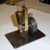
Showing the 'turned column' seating although at the reqd 8 degrees is not square across the casting. Although after milling the bottom of the Sole Plate flat will hopefully help with this.
Regards. Allan. |
| GarryC | 10/04/2014 13:17:12 |
740 forum posts 1043 photos | A little more thought on this and remembering the rule when machining castings and measuring in relation to surfaces that will remain un-machined (hope thats right) - so to get the Sole Plate bottom milled flat I think now to start with the Sole Plate upturned and resting on parallels across the top of Sole Plate frame.. That's a big taper in the Sole Plate base thickness showing in that last photo.. Good thing I gave this lots of thought and didn't jump straight in I think.. Cheers. Allan Edited By Allan. on 10/04/2014 13:23:15 |
| JasonB | 10/04/2014 13:27:28 |
25215 forum posts 3105 photos 1 articles | With the bearing housings being a fair distance from the ends of the casting you may not end up with the most stable setup to machine the underside. I think I would use packing under the 4 corners and then machine the bottom first, feeler gauges come in handy to fine tune the position of the casting. I would think that a between ctrs bar is the best option, you may find you get some chatter if trying to come in from one end only as the tool will nee dto be about 4" long to reach right through. One thing I like to do on castings like this is bolt them to a machining plate as this will give you straight edges that can be used to clock the casting true as you move it between mill and lathe. EDIT you were thinking the same as me while I was typing
J Edited By JasonB on 10/04/2014 13:28:22 |
| GarryC | 10/04/2014 13:38:33 |
740 forum posts 1043 photos | Your good sense must be starting to rub off on me! ...and the 'Machining plate' sounds like very good advice. Thanks Jason. Cheers Allan. Edited By Allan. on 10/04/2014 13:40:34 |
| GarryC | 11/04/2014 12:32:14 |
740 forum posts 1043 photos | Just managed to mill the Sole Plate bottom flat today.. The casting is not particularly 'square' whichever way it's measured and looked to have a noticeable taper across the width - it looks fine to the eye now though, I found the best way to mill the bottom after all was to simply up turn onto the bearing housings, (resting on parallels across the frame was very unstable when I tried that). Trying to take off as little as possible I ending up taking several cuts totalling 90 thou before it was sitting square. Everything will now be milled with reference to the base and hopefully be ok.. Setting up to mill the Sole Plate bottom flat.
The Box Bed and Sole Plate after milling.
The Box Bed and Sole Plate so far.
Regards. Allan. ps. trying to make at least a little progress most days.. Edited By Allan. on 11/04/2014 12:35:25 |
| GaryM | 11/04/2014 14:25:33 |
 314 forum posts 44 photos | Hi Allan, I'll be following your build with interest, especially as I fell down the stairs last Monday and broke my ankle Gary |


This thread is closed.
Magazine Locator
Want the latest issue of Model Engineer or Model Engineers' Workshop? Use our magazine locator links to find your nearest stockist!
Sign up to our Newsletter
Sign up to our newsletter and get a free digital issue.
You can unsubscribe at anytime. View our privacy policy at www.mortons.co.uk/privacy
Latest Forum Posts
- *Oct 2023: FORUM MIGRATION TIMELINE*
05/10/2023 07:57:11 - Making ER11 collet chuck
05/10/2023 07:56:24 - What did you do today? 2023
05/10/2023 07:25:01 - Orrery
05/10/2023 06:00:41 - Wera hand-tools
05/10/2023 05:47:07 - New member
05/10/2023 04:40:11 - Problems with external pot on at1 vfd
05/10/2023 00:06:32 - Drain plug
04/10/2023 23:36:17 - digi phase converter for 10 machines.....
04/10/2023 23:13:48 - Winter Storage Of Locomotives
04/10/2023 21:02:11 - More Latest Posts...
- View All Topics
Support Our Partners


Shopping Partners
Subscription Offer

Latest "For Sale" Ads
- Reeves** - Rebuilt Royal Scot by Martin Evans
by John Broughton
£300.00 - BRITANNIA 5" GAUGE James Perrier
by Jon Seabright 1
£2,500.00 - Drill Grinder - for restoration
by Nigel Graham 2
£0.00 - WARCO WM18 MILLING MACHINE
by Alex Chudley
£1,200.00 - MYFORD SUPER 7 LATHE
by Alex Chudley
£2,000.00 - More "For Sale" Ads...
Latest "Wanted" Ads
- D1-3 backplate
by Michael Horley
Price Not Specified - fixed steady for a Colchester bantam mark1 800
by George Jervis
Price Not Specified - lbsc pansy
by JACK SIDEBOTHAM
Price Not Specified - Pratt Burnerd multifit chuck key.
by Tim Riome
Price Not Specified - BANDSAW BLADE WELDER
by HUGH
Price Not Specified - More "Wanted" Ads...
Get In Touch!
Do you want to contact the Model Engineer and Model Engineers' Workshop team?
You can contact us by phone, mail or email about the magazines including becoming a contributor, submitting reader's letters or making queries about articles. You can also get in touch about this website, advertising or other general issues.
Click THIS LINK for full contact details.
For subscription issues please see THIS LINK.
Digital Back Issues


Donate

 Register
 Log-in
Model Engineer Magazine
- Percival Marshall
- M.E. History
- LittleLEC
- M.E. Clock

ME Workshop
- An Adcock
- & Shipley
- Horizontal
- Mill

Subscribe Now
- Great savings
- Delivered to your door

Pre-order your copy!
- Delivered to your doorstep!
- Free UK delivery!
All Forum Topics > Work In Progress and completed items > Stuart 'No.1' : a beginners tale..