Forum sponsored by:

Mercer Dial Indicator
| Kenneth Lindeman | 06/02/2014 06:59:40 |
 37 forum posts 5 photos | I pick up this at a sale and was wondering if anybody knew how it worked It's a Mercer model 107A dial indictor set |
| Kenneth Lindeman | 06/02/2014 07:01:31 |
37 forum posts 5 photos |
|
| john kennedy 1 | 06/02/2014 07:17:58 |
 214 forum posts 24 photos | Looks like a comparator to me. You use the clamp on the edge of a surface plate and the clock on the clamp. Components are then slid under the stylus to compare. I think ? |
| mechman48 | 06/02/2014 09:34:17 |
 2947 forum posts 468 photos | Last time I used one of these set ups was for reverse alignment readings on Turbine - gearbox - pump etc. alignment; the clamp was fixed to the relevant coupling flange, the dial indicator was placed either on the rim or face of the opposite coupling .. depending whether you were taking rim or face reading.. a sweep taken from top to bottom .. resultant reading divided by 2 gave you offset from centre line + or - .xxxx" reverse set up & repeat you then calculated, shimmed, or moved driver / driven appropriately.. horizontally or vertically, allowing for thermal expansion etc. to attain desired alignment. The cross bar was used in the same manner but on an internal bore diameter.. etc. etc. Have also used it as a comparator on surface plate when I was in toolroom as John mentioned, also used it to check for any shaft run out /bend when shaft set up on vee blocks .. so multiple uses, can be adapted to suit work. p.s. You shouldn't clamp anything to a surface plate, CI or granite, use the long bar with the vertical post or magnetic stand (& we've all done it Cheers George. Edited By mechman48 on 06/02/2014 09:40:29 |
| Ian S C | 06/02/2014 11:16:10 |
 7468 forum posts 230 photos | It looks similar to a beat up one that I got some years ago, if it is the contact is a rod sticking out the back of the instrument. Just been out to the workshop, and bought it in, and find that my one has "The L.S.Starrett Co. Athol Mass U.S.A.. It's 1 3/8" dia, and reads .001". Sorry getting OT. Ian S C |
| Nobby | 06/02/2014 12:54:04 |
 587 forum posts 113 photos | Hi |
| Clive Foster | 07/02/2014 00:08:26 |
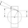
| 3630 forum posts 128 photos | Picture shows the tilting "see-saw" extension device from my Starrett Last Word accessory set used with a standard plunger indicator to pick up an internal taper whent setting the taper turning attachment on my Smart & Brown 1024 VSL lathe. Your Mercer set includes an essentially identical device.
Normally the mounting spigot on the indicator is fitted into the empty hole in the pivoting lever mount with the indicator arranged so the free end of the see-saw pushes the indicator plunger. I could have set things up using the Starrett indicator but it would have obscured the view of the taper somewhat and the spare length of mounting rod projecting through the fixing hole would have reduced the amount of gauging travel. Important in this case because there was a parallel bore around 1/2 inch long before the taper began. The Smart & Brown has plenty of real estate on its massive cross slide to hang things off an old style Eclipse magnetic base as shown which facilitated switching to a tenths thou indicator for final setting up. More rods and clamps involved tho' so much more fiddly. The rectangular bar and rod are provided to facilitate mounting in a toolpost but can be creatively used in many other ways. Clive
|
| Michael Gilligan | 07/02/2014 09:06:23 |
 23121 forum posts 1360 photos | Clive, That's a very useful photo of the set-up ... Nicely done, Sir. MichaelG. |
| Howard Lewis | 07/02/2014 09:51:37 |
| 7227 forum posts 21 photos | You have a useful piece of kit there. The black rectangular bar, (with the 1/4 or 5/16" spindle attached) can be fitted onto a Height Gauge, for use on a Surface Plate or table. It can also be clamped (carefully, and preferably protected on both dises) in a toolpost on the lathe. The clamp will allow it to be fitted in a variety of places, but as has already been said, not to Surface plate or table. The DTI can be used as a normal Plunger Clock, or as others have said, to check run out, (or position) of bores, using the pivoting accessory. Quite versatile, you will find it very useful as time goes on. Well Done for a good find! Howard
|
| Kenneth Lindeman | 07/02/2014 10:40:56 |
37 forum posts 5 photos | Thanks for all the feedback. I will be trying it out this weekend. I also have a normal clock on magnetic base. I am sure I will be able to align anything now. O I forgot My favorite the edge finder. |
| Kenneth Lindeman | 14/02/2014 06:10:53 |
37 forum posts 5 photos | Here is a very interesting piece I found on how to make your own extension for your dial indicator http://www.homemadetools.net/dial-indicator-holder-5 |
| Michael Gilligan | 14/02/2014 09:04:44 |
23121 forum posts 1360 photos | Thanks for the link, Kenneth That's quite tidy, and [re: the ongoing discussion about short articles in MEW] it nicely demonstrates what can be presented in half a page. MichaelG. |


Please login to post a reply.
Magazine Locator
Want the latest issue of Model Engineer or Model Engineers' Workshop? Use our magazine locator links to find your nearest stockist!
Sign up to our Newsletter
Sign up to our newsletter and get a free digital issue.
You can unsubscribe at anytime. View our privacy policy at www.mortons.co.uk/privacy
Latest Forum Posts
- hemingway ball turner
04/07/2025 14:40:26 - *Oct 2023: FORUM MIGRATION TIMELINE*
05/10/2023 07:57:11 - Making ER11 collet chuck
05/10/2023 07:56:24 - What did you do today? 2023
05/10/2023 07:25:01 - Orrery
05/10/2023 06:00:41 - Wera hand-tools
05/10/2023 05:47:07 - New member
05/10/2023 04:40:11 - Problems with external pot on at1 vfd
05/10/2023 00:06:32 - Drain plug
04/10/2023 23:36:17 - digi phase converter for 10 machines.....
04/10/2023 23:13:48 - More Latest Posts...
- View All Topics
Support Our Partners


Shopping Partners
Subscription Offer

Latest "For Sale" Ads
- Reeves** - Rebuilt Royal Scot by Martin Evans
by John Broughton
£300.00 - BRITANNIA 5" GAUGE James Perrier
by Jon Seabright 1
£2,500.00 - Drill Grinder - for restoration
by Nigel Graham 2
£0.00 - WARCO WM18 MILLING MACHINE
by Alex Chudley
£1,200.00 - MYFORD SUPER 7 LATHE
by Alex Chudley
£2,000.00 - More "For Sale" Ads...
Latest "Wanted" Ads
- D1-3 backplate
by Michael Horley
Price Not Specified - fixed steady for a Colchester bantam mark1 800
by George Jervis
Price Not Specified - lbsc pansy
by JACK SIDEBOTHAM
Price Not Specified - Pratt Burnerd multifit chuck key.
by Tim Riome
Price Not Specified - BANDSAW BLADE WELDER
by HUGH
Price Not Specified - More "Wanted" Ads...
Get In Touch!
Do you want to contact the Model Engineer and Model Engineers' Workshop team?
You can contact us by phone, mail or email about the magazines including becoming a contributor, submitting reader's letters or making queries about articles. You can also get in touch about this website, advertising or other general issues.
Click THIS LINK for full contact details.
For subscription issues please see THIS LINK.
Digital Back Issues


Donate

 Register
 Log-in
Model Engineer Magazine
- Percival Marshall
- M.E. History
- LittleLEC
- M.E. Clock

ME Workshop
- An Adcock
- & Shipley
- Horizontal
- Mill

Subscribe Now
- Great savings
- Delivered to your door

Pre-order your copy!
- Delivered to your doorstep!
- Free UK delivery!
All Forum Topics > General Questions > Mercer Dial Indicator