Forum sponsored by:

Rotary table inspiration....
| Chris Parsons | 04/12/2013 09:25:52 |
 118 forum posts 37 photos | Thought it was about time my new (well, new to me!) rotary table got some use... I have a 4 inch table that, unusually it seems, has three not four T slots - which does make things a bit awkward when trying to clamp things down. So I thought about making a face plate with some threaded holes that I can attach to the existing table (with countersunk screws) - but am thinking about the best layout of the holes, initial thinking was two rows at 90 degrees to each other aligned with the axis but now I am wondering whether two parallel rows at 90 degrees centred on the axis might be better? The idea being I could centre a bar along the axis and use the holes either side to clamp it down for instance? Another thought is the size of the face plate - if I decide to fit a chuck I guess I would make a four inch plate and buy a three inch chuck to give me a flange to bolt it down, but could make the 'threaded hole' plate bigger? (would make it difficult to reach the locking clamps if it was too big) Howard Hall has an excellent article on his website about making a centre plate with a set of spigots which I will make to fit the three slots but will still have the clamping down problem. The RT also has a 2MT hole so Howards adaptor will help me with centering workpieces on the axis - by making a adaptor to turn the 2MT hole into a parallel one which he also suggests in the article. Any ideas/observations would be gratefully received! Chris
Edited By Chris Parsons on 04/12/2013 09:27:04 |
| John Stevenson | 04/12/2013 09:32:13 |
 5068 forum posts 3 photos | I have a quite useful jig plate here, not on a RT but still used a lot. It has the tapped holes set in 4 quadrants. NE and SW are in a grid pattern equal from either imaginary cross line. NW and SE are set radially in rings. It's about 10" and the holes are on 3/4" or 20mm centres approx. No idea what it came off but it was part of a machine at some point. Edited By John Stevenson on 04/12/2013 09:32:58 |
| Michael Gilligan | 04/12/2013 10:05:09 |
 23121 forum posts 1360 photos | Chris, You have a 4 inch table ... Will your Adapter Plate also need to be 4" diameter? ... It may be worth considering a modest overhang, and perhaps a different shape. MichaelG. |
| Chris Parsons | 04/12/2013 11:08:47 |
118 forum posts 37 photos | Thanks for the comments
John, your jig plate sounds interesting - think I can visualise it, grid and radial holes sound like an excellent idea, and perhaps not too hard to make, although 10 inches would be a bit big perhaps Michael - no, it could be bigger but I need to be able to reach the locking clamps - although I could make longer levers, and I guess it doesn't have to be round One issue I have had is sometimes the clamps tighten themselves up when cranking around and I sometimes remove them (depending on how annoying it gets) Need to have a ponder methinks! I have just found and ordered a 100mm chuck with 3 front mounting holes from RDG which should hopefully fit nicely - someone suggested this a while ago which is a good idea Regards Chris
Edited By Chris Parsons on 04/12/2013 11:11:02 |
| Martin W | 04/12/2013 11:32:31 |
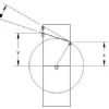
| 940 forum posts 30 photos | Chris I have a 4"/100mm table marketed under the Vertex label with 3 slots. Some time ago I bought a 100m 3 jaw chuck from RDG and mounted this on the table. The only problem I have had is that the T nuts I made needed rounding/radiusing to clear the locking lugs on the table. As the table has an MT2 taper I can set the chuck, central to the table rotational axis, quickly by using a 2MT test bar and gently gripping this with the chuck before tightening the securing screws. While this may not satisfy the purists it is certainly a good starting point for final centring of the chuck. Martin Edited By Martin W on 04/12/2013 11:33:59 |
| Michael Gilligan | 04/12/2013 12:09:32 |
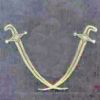
23121 forum posts 1360 photos | Chris, The reason I hinted at making the plate with some overhang [aside from the obvious increase in Real Estate], is that it gives the option to use hooked bolts to clamp-down long bars. Also worthing mentioning: If you make the plate reasonably thick, you can drill & tap the edges, which gives extra options. ... Thinking about it further; I would make two adapter plates [each 5-6" across]
That done ... Sod's Law dictates that you will probably want to clamp-down some Pentagons. MichaelG. . Yes folks; I know that [2] is an Octogon, of sorts ...but I don't mean a regular one, and I can't remember the technically correct name.
Edited By Michael Gilligan on 04/12/2013 12:11:08 |
| Gone Away | 04/12/2013 18:13:18 |
| 829 forum posts 1 photos | octagon-with-unequal-sides-thingy |
| Stub Mandrel | 04/12/2013 18:23:01 |
 4318 forum posts 291 photos 1 articles | Octagonoid? Neil
|
| jason udall | 04/12/2013 19:48:01 |
| 2032 forum posts 41 photos | Octagon.8 sided figure. REGULAR Octagon 8 equal sides at equal angles |
| Rik Shaw | 04/12/2013 19:54:29 |
 1494 forum posts 403 photos | Eight nuts Neil - and its spelt "Octagonad" |
| Speedy Builder5 | 04/12/2013 20:16:52 |
| 2878 forum posts 248 photos | Perhaps think about a 4 jaw self centering chuck - just gives a little more support when milling. |
| Michael Gilligan | 04/12/2013 20:26:50 |
23121 forum posts 1360 photos | Posted by jason udall on 04/12/2013 19:48:01:
Octagon.8 sided figure. REGULAR Octagon 8 equal sides at equal angles . I suppose it depends whose definition you use Wikipedia is certainly more specific. and yes, I know I spelled it wrong, but it was too late to edit. MichaelG. |
| Stub Mandrel | 04/12/2013 20:32:48 |
4318 forum posts 291 photos 1 articles | I thought they had eight tentacles, Rik! Neil |
| Michael Gilligan | 04/12/2013 21:38:52 |
23121 forum posts 1360 photos | Chris, Back to your question ... I would also suggest making a third plate ... any shape & size that's convenient, and undrilled [except for its fixings to the table]. This is the one that you drill & tap to suit the really awkward jobs. When it finally resembles a Swiss Cheese, just throw it away and make another. MichaelG. |
| john kennedy 1 | 05/12/2013 07:26:19 |
 214 forum posts 24 photos | Posted by Martin W on 04/12/2013 11:32:31:
As the table has an MT2 taper I can set the chuck, central to the table rotational axis, quickly by using a 2MT test bar and gently gripping this with the chuck before tightening the securing screws.
What a great idea,saves messing about making a precise fitting plug .. John |
| Paul Janes | 05/12/2013 11:06:57 |
| 23 forum posts 3 photos | Your mounting plate can be larger than your rotary table. Just depends on how rigid it is. I have a 6" rotary table on which I bolted a much larger plate. The plate locates on the centre spigot and is restrained by 4 countersunk cap screws and tee nuts. I then tapped some holes and used my mill clamps to hold the job.
Edited By Paul Janes on 05/12/2013 11:08:07 |


Please login to post a reply.
Magazine Locator
Want the latest issue of Model Engineer or Model Engineers' Workshop? Use our magazine locator links to find your nearest stockist!
Sign up to our Newsletter
Sign up to our newsletter and get a free digital issue.
You can unsubscribe at anytime. View our privacy policy at www.mortons.co.uk/privacy
Latest Forum Posts
- *Oct 2023: FORUM MIGRATION TIMELINE*
05/10/2023 07:57:11 - Making ER11 collet chuck
05/10/2023 07:56:24 - What did you do today? 2023
05/10/2023 07:25:01 - Orrery
05/10/2023 06:00:41 - Wera hand-tools
05/10/2023 05:47:07 - New member
05/10/2023 04:40:11 - Problems with external pot on at1 vfd
05/10/2023 00:06:32 - Drain plug
04/10/2023 23:36:17 - digi phase converter for 10 machines.....
04/10/2023 23:13:48 - Winter Storage Of Locomotives
04/10/2023 21:02:11 - More Latest Posts...
- View All Topics
Support Our Partners


Shopping Partners
Subscription Offer

Latest "For Sale" Ads
- Reeves** - Rebuilt Royal Scot by Martin Evans
by John Broughton
£300.00 - BRITANNIA 5" GAUGE James Perrier
by Jon Seabright 1
£2,500.00 - Drill Grinder - for restoration
by Nigel Graham 2
£0.00 - WARCO WM18 MILLING MACHINE
by Alex Chudley
£1,200.00 - MYFORD SUPER 7 LATHE
by Alex Chudley
£2,000.00 - More "For Sale" Ads...
Latest "Wanted" Ads
- D1-3 backplate
by Michael Horley
Price Not Specified - fixed steady for a Colchester bantam mark1 800
by George Jervis
Price Not Specified - lbsc pansy
by JACK SIDEBOTHAM
Price Not Specified - Pratt Burnerd multifit chuck key.
by Tim Riome
Price Not Specified - BANDSAW BLADE WELDER
by HUGH
Price Not Specified - More "Wanted" Ads...
Get In Touch!
Do you want to contact the Model Engineer and Model Engineers' Workshop team?
You can contact us by phone, mail or email about the magazines including becoming a contributor, submitting reader's letters or making queries about articles. You can also get in touch about this website, advertising or other general issues.
Click THIS LINK for full contact details.
For subscription issues please see THIS LINK.
Digital Back Issues


Donate

 Register
 Log-in
Model Engineer Magazine
- Percival Marshall
- M.E. History
- LittleLEC
- M.E. Clock

ME Workshop
- An Adcock
- & Shipley
- Horizontal
- Mill

Subscribe Now
- Great savings
- Delivered to your door

Pre-order your copy!
- Delivered to your doorstep!
- Free UK delivery!
All Forum Topics > Workshop Tools and Tooling > Rotary table inspiration....