Forum sponsored by:

Crossing out with CNC
| Russell Eberhardt | 18/11/2013 20:19:58 |
 2785 forum posts 87 photos | Having spent hours with the piercing saw on my last clock I thought I would try cnc profiling for crossing out the wheels on my English Regulator. I drew up the cutting path using Draftsight, exported a DXF file, and used DXF2GCODE to generate the gcode file. That took about ten minutes. Then to the mill. I used a dowel in the chuck to centre the wheel in the zero position before clamping, changed to a 2 mm end mill and off we go:
The machining of a 2 1/2 inch diameter wheel took 24 min. Taking it very slowly and making the cut in 3 stages with a 2 mm slot drill. The result wasn't quite what I had hoped for:
I had clamped it to a thin MDF board and didn't allow for the fact that the wheel would bend by a few thou due to the resilience of the MDF. Still a few minutes with the saw and needle files soon fixed it. The next one came out better with a deeper final cut. Russell. P.S. A new somewhat improved version of DXF2GCODE was released a few days ago. Edited By Russell Eberhardt on 18/11/2013 20:24:04 |
| Niloch | 18/11/2013 21:32:41 |
| 371 forum posts | Tapered 'spokes' would look so very much more elegant. |
| John Stevenson | 18/11/2013 22:09:48 |
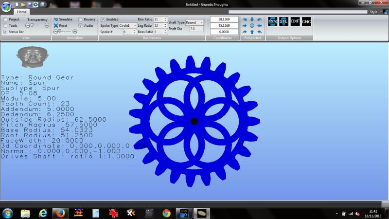
 5068 forum posts 3 photos | Take a look at Gearotic Thought, the successor to Gearotic Motion by Art Fenarty of Mach 3 fame.
This has been updated to have 42 different types of spokes.
As well as all the different styles you can choose how many spokes, alter the rim ratio, leg ratio and boss ratio. This means that a given design can further be spawned off into unlimited designs by playing with these ratios.
Once designed you can get a DXF from it or even get Gearotic to spit the G-Code out directly. It's getting to be a very powerful gear design software tool. |
| Russell Eberhardt | 18/11/2013 22:43:45 |
2785 forum posts 87 photos | Yes, tapered spokes would look more elegant but I don't think you could get enough taper for it to look good without either weakening it or increasing the weight. For the lower wheels in the train it's most important to minimise weight in order to reduce the pivot friction, for the escape wheel the moment of inertia is probably more important due to the intermittent motion. I'm not clever enough to calculate the exact requirements though. My clock will be driven by a 15 or 16 lb weight so the strength is important. Interesting link, John. That looks to be a very comprehensive program. I must have a good look at the demo. Russell. |
| Ian P | 19/11/2013 08:08:30 |
 2747 forum posts 123 photos | Russell Can I ask what make/size of mill you used? Also what level of 'repeatable' precision/tolerance you achieve? I have a project that requires a quantity of small brass CNC components but they need to fit together to quite a high tolerance, Is +/-0.01 doable? The wheel you show looks really good, you going to remove the cutter radii in the corners by filing? It would make a big difference to the appearance Ian P |
| Russell Eberhardt | 19/11/2013 08:56:49 |
2785 forum posts 87 photos | Ian, The mill I used was a Seig SX2 Plus which I converted for cnc. See this thread on another forum. The convererted mill has about 1 thou backlash on the X and Y axes and I've just done some measurements on one of my wheels and the biggest error I get is 3 thou which sounds about right. I expect John will come back with some advice but I would guess that you will need a much more rigid machine if you want 0.01 mm tolerance. If I put a dial gauge on the side of the spindle and lean on the head I get about 0.06 mm movement due to the column flexing. Yes, sharp corners are traditional but a radius is a better engineering solution. I will of course file and polish the edges but I might leave the radius. I'm trying to build a precision clock rather than an exhibition winner! Russell. |
| roy entwistle | 19/11/2013 09:15:31 |
| 1716 forum posts | Russell I reckon that I can cross out a wheel in about 10 minutes using traditional methods and if done correctly there should be very little cleaning up with files to be done Also an English regulator should run on about 7lb assuming its 7day going and not a monthly one My own regulator runs on 5lbs The only variation in time keeping is because the invar pendulum rod expands with cold and contracts with heat Roy |
| Ian P | 19/11/2013 09:40:28 |
2747 forum posts 123 photos | Russell Thanks for that, I think my 0.01mm might be pipe dream! Apart from the accuracy I want to get a really fine surface finish to minimises hand finishing. It probably need a large rigid machine, and a reasonably constant temperature I imagine.
Roy Crossing out in 10 minutes, Wow! By traditional methods are you including, marking out, drilling holes, piercing saw, filing etc.? If so you are fast worker! I thought the whole idea of Invar was its very small coefficient of expansion? Ian P |
| John Stevenson | 19/11/2013 10:24:23 |
5068 forum posts 3 photos | Ian, 0.01 is 4 tenths of a thou, can you work consistently to that by hand using home shop machinery ?
If not then why would you expect CNC to better the accuracy of a base machine ?
CNC is good for repeatability it cannot replace basic accuracy. |
| Ian P | 19/11/2013 10:45:13 |
2747 forum posts 123 photos | John I did use the expression pipedream! Also I did not know the accuracy of the machine Russell used, that's why I asked. Yes, I can work by hand consistently to half a thou but not every day all day. One thing CNC should do is to work to the same standard all the time. It might make rubbish parts but they would all be rubbish to the same standard. A Stepper type CNC conversion of a ''hobby' machine is not likely to make it more accurate but it might be significantly improved if it was converted with true servomotors and proper feedback. Ian P
|
| Russell Eberhardt | 19/11/2013 11:25:41 |
2785 forum posts 87 photos | Posted by roy entwistle on 19/11/2013 09:15:31:
Russell I reckon that I can cross out a wheel in about 10 minutes using traditional methods and if done correctly there should be very little cleaning up with files to be done Also an English regulator should run on about 7lb assuming its 7day going and not a monthly one My own regulator runs on 5lbs The only variation in time keeping is because the invar pendulum rod expands with cold and contracts with heat Roy This is only my second clock and on the first one it took me well over an hour to cross out each wheel by hand. Perhaps I need more practice! My great great grandfather made clocks all his life so he could have taught me something. My English regulator is a month going one. I'm using an invar pendulum with a temperature compensator in the bob. The other factor effecting time keeping is varying friction. I hope to minimise that by using miniature ball bearings for the pivots. Russell. Edited By Russell Eberhardt on 19/11/2013 11:27:30 |
| Andrew Johnston | 19/11/2013 11:47:58 |
 7061 forum posts 719 photos | Ian, It might just about be possible to hold ±0.01mm, but I wouldn't bet the ranch on it. I've just measured 10 off, selected at random, of the steel front spokes for my traction engine. The arms are nominally 0.750" wide and I wanted them to be a snug fit in the hubs without needing loads of filing; the results were: 0.7500 0.7510 0.7510 0.7510 0.7515 0.7506 0.7505 0.7505 0.7505 0.7505 I had several trial runs making adjustments to the tolerances in the CAM program and trading off stock left between roughing and finishing cycles before achieving these results. I also changed cutters, as the original carbide cutter wore out very quickly and gave a lousy finish. With the new cutter I achieved a finish of 0.45µm Ra. Once sorted all the spokes were machined in one session to minimise the effects of temperature. I might had done a bit better if I'd changed cutters between roughing and finishing. Some of the things you would need to take into account are: 1. Rigidity and accuracy of the machine 2. Adjustment of the gibs and backlash in the slides 3. Tolerance of the tool, both as new and wear - for instance the 6mm cutter I used for the spokes is spec'd as +0.000/-0.050mm on diameter 4. Temperature of everything, the machine, work, jigging, heat put into the job during machining etc. 5. Tool deflection - could easily be 0.01mm depending upon the tool material, tool diameter and cutting parameters 6. Temperature of the measurement equipment and environment 7. The machining path, irrespective of the type of drive acceleration and deceleration of the machine table can significantly affect accuracy And probably a load of other things! In my (limited) experience the average professional CNC machine shop doesn't hold ±0.01mm as a matter of course. I've measured two large (300mm square) heatsinks, one machined by me in my garage, and one machined by a professional CNC machine shop to my design. I can't remember the exact figures but I think I was generally around ±0.05mm, while the professionals were around ±0.03mm. They fouled up on flatness and finish in some important areas though, so we rejected the parts. I doubt that a servo mechanism would be inherently more accurate. If I understand it correctly the simpler servo mechanisms use feedback encoders on the motors, so basic accuracy is still dependent upon the accuracy of the ballscrews. Of course if the servo uses independent feedback from movement of the slideways then it may well be more accurate. I'd try and redesign the parts so they don't need to be so accurate. Regards, Andrew |
| John Stevenson | 19/11/2013 13:03:51 |
5068 forum posts 3 photos | Thank you Andrew, This was a most practical post.
One thing to bear in mind is that using Andrews heat sink as an example, he got 0.05 using a high end home shop machine, a Tormach to be exact.
The professionals got 0.03 but and a big but their machine probably cost X 5 times to achieve an increase in accuracy of 0.02.
You can hit 0.01 but it's at a high cost or either time or rejects. Unless that accuracy is absolutely needed Andrews last line is very relevant.
I wonder what tolerance Roy achieves given he does a wheel in 10 minutes ? |
| Ian P | 19/11/2013 14:11:30 |
2747 forum posts 123 photos | Andrew I'm quite impressed with your results and your reply explains really well the details and nuances of CNC machining. I've decided it not for me... yet. There is not a lot of scope for a redesign of the parts I have been asked to supply and I was considering making them myself. Only some of the dimensions and surfaces are the critical ones so it might be be that some hand fitting is required. I have little experience in getting quotes from CNC capable companies but the first replies I have got lead me to the conclusion that the product would be too expensive to be viable. The customer who want the parts has ideas as to what it would sell for. I was thinking of encoders directly driven by the table but its not exactly a DIY CNC conversion. The other aspect of pro CNC is that its not just the machine, it needs all the facilities of a metrology department to get results to a consistent standard. Ian P |
| NJH | 19/11/2013 14:19:44 |
 2314 forum posts 139 photos | John I suspect that Roy would think that he produces his clock wheels to adequate levels of precision!
Russell Working quickly and accurately by hand is not something that comes quickly but, like those posting on other threads say, it is a skill developed over time and once learned is not forgotten. OK using CNC may be accurate and fast - if you are going to make lots of clock wheels the same or , indeed, I guess it might be an interesting exercise in machining / programming. The thing is though nobody NEEDS to build a clock. Visit your local pound store and you are likely to find a clock there which is far more accurate than one you will make. So construction of an English Regulator will test your skills and the outcome will be something of beauty that will out last you and many more accurate "modern" clocks. It will be a modern antique! Do you want your descendants to say "what a skilled old boy he was" or "surprising that the computers could do that in the olden days? Hey well it's all about enjoying the journey - however you choose to travel. Regards Norman
|
| Andrew Johnston | 19/11/2013 15:47:20 |
7061 forum posts 719 photos | Posted by Ian Phillips on 19/11/2013 14:11:30:
Andrew I'm quite impressed with your results........................ Only 'quite', ah well must try harder. Commercial CNC is often uneconomic for parts that have been designed without CNC in mind from the start. For parts I've designed, and seen from other people, quite simple changes can make a huge difference in machining cost. If a part can be machined at one setting rather than two or three it's going to be a lot cheaper. The changes may be as simple as adding a radius in some places. Regards, Andrew |
| Ian P | 19/11/2013 16:33:45 |
2747 forum posts 123 photos | Andrew 'Quite' is high praise indeed from me! It was the first word that appeared on the screen when I typed. I designed the main part so that it could all be done with one cutter size and did adjust various other bits which to my thinking made it easier to machine. Not having CNC experience though, I might not be looking at the problem from the right direction. I dont know the trade-off between cutter changes for hogging out and finishing. I presume if a part requires re-mounting for some operations it is the manual aspect that adds to the cost. As a general question, would it make sense to submit a drawing where a whole batch of identical parts were machined out of one bar but left attached, for me to later separate and machine the last face? Ian P
|
| Michael Gilligan | 19/11/2013 17:12:30 |
 23121 forum posts 1360 photos | Posted by Ian Phillips on 19/11/2013 09:40:28:
I thought the whole idea of Invar was its very small coefficient of expansion? Ian P . Ian, For info.
In conventional Engineering terms, these are very small changes indeed ... but when you think that the best Regulators were capable of keeping time within about 30 seconds per year, such changes become significant. [it's worth working out what that represents as a percentage accuracy] MichaelG.
|
| Stub Mandrel | 19/11/2013 18:59:57 |
 4318 forum posts 291 photos 1 articles | Andrew, Seems you were cutting a tad oversize: 0.7495 0.7500 * 0.7505 ***** 0.7510 *** 0.7515 * 0.7520 Suspiciously close to a normal distribution for such a small sample Reminds me of A-Llevel chemistry practical exam "It doesn't matter exactly what readings you get, as long as they are all grouped within 0.1cc" Norman Do you want your descendants to say "what a skilled old boy he was" or "surprising that the computers could do that in the olden days? I just hope mine can tell teh difference between the models and the junk.
Neil
|
| Ian P | 19/11/2013 19:59:24 |
2747 forum posts 123 photos | Michael If it can have sudden (at random) changes then I'm amazed it was ever accepted by horologists unless at the time it was in favour the effect was too small to be detected. Batch to batch differences can be adjusted for, but random changes would render all the effort of making and calibrating the timekeeping device into a wasted effort. If I had a bit more time (not a pun) its something I would read up on.
Ian P
|


Please login to post a reply.
Magazine Locator
Want the latest issue of Model Engineer or Model Engineers' Workshop? Use our magazine locator links to find your nearest stockist!
Sign up to our Newsletter
Sign up to our newsletter and get a free digital issue.
You can unsubscribe at anytime. View our privacy policy at www.mortons.co.uk/privacy
Latest Forum Posts
- *Oct 2023: FORUM MIGRATION TIMELINE*
05/10/2023 07:57:11 - Making ER11 collet chuck
05/10/2023 07:56:24 - What did you do today? 2023
05/10/2023 07:25:01 - Orrery
05/10/2023 06:00:41 - Wera hand-tools
05/10/2023 05:47:07 - New member
05/10/2023 04:40:11 - Problems with external pot on at1 vfd
05/10/2023 00:06:32 - Drain plug
04/10/2023 23:36:17 - digi phase converter for 10 machines.....
04/10/2023 23:13:48 - Winter Storage Of Locomotives
04/10/2023 21:02:11 - More Latest Posts...
- View All Topics
Support Our Partners


Shopping Partners
Subscription Offer

Latest "For Sale" Ads
- Reeves** - Rebuilt Royal Scot by Martin Evans
by John Broughton
£300.00 - BRITANNIA 5" GAUGE James Perrier
by Jon Seabright 1
£2,500.00 - Drill Grinder - for restoration
by Nigel Graham 2
£0.00 - WARCO WM18 MILLING MACHINE
by Alex Chudley
£1,200.00 - MYFORD SUPER 7 LATHE
by Alex Chudley
£2,000.00 - More "For Sale" Ads...
Latest "Wanted" Ads
- D1-3 backplate
by Michael Horley
Price Not Specified - fixed steady for a Colchester bantam mark1 800
by George Jervis
Price Not Specified - lbsc pansy
by JACK SIDEBOTHAM
Price Not Specified - Pratt Burnerd multifit chuck key.
by Tim Riome
Price Not Specified - BANDSAW BLADE WELDER
by HUGH
Price Not Specified - More "Wanted" Ads...
Get In Touch!
Do you want to contact the Model Engineer and Model Engineers' Workshop team?
You can contact us by phone, mail or email about the magazines including becoming a contributor, submitting reader's letters or making queries about articles. You can also get in touch about this website, advertising or other general issues.
Click THIS LINK for full contact details.
For subscription issues please see THIS LINK.
Digital Back Issues


Donate

 Register
 Log-in
Model Engineer Magazine
- Percival Marshall
- M.E. History
- LittleLEC
- M.E. Clock

ME Workshop
- An Adcock
- & Shipley
- Horizontal
- Mill

Subscribe Now
- Great savings
- Delivered to your door

Pre-order your copy!
- Delivered to your doorstep!
- Free UK delivery!
All Forum Topics > Clocks and Scientific Instruments > Crossing out with CNC