Forum sponsored by:

Governor pin joints
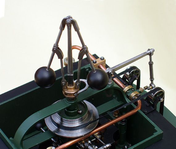
A method of making unobtrusive joints in governor linkages and similar.
| Maurice | 10/06/2013 23:12:13 |
| 469 forum posts 50 photos | I thought my method of making pin joints in governor linkages might be of interest. Trying to copy full size practice can look clumsy. Mine are made from standard taper pins. First the joints are made and drilled undersize. With the joint assembled, a taper pin reamer is used to enlarge the hole to a suitable size. When happy with the appearance, the joint is taken apart, and the centre portion is reamed a little more. Reassemble the joint and try the fit. A light tap with a small hammer, with the joint supported, will fix the pin in place. Try for free movement. If it's too stiff, take it apart and ream a little more from the centre part. If the fit is too sloppy, the ream the complete joint. The actual joint pin is a short piece of a taper pin. I shorten the thin end first, and round it over with circular strokes on an oil stone. I then lightly drive the pin into a tapered hole in a spare bit of rod to do the thicker end. A medium domed shape seems satisfactory, but a hemishere can be achieved if preferred. The result can be seen in the photo. The rest of the engine can be seen in my album if you are interested.
Maurice, |
| JasonB | 11/06/2013 07:38:05 |
 25215 forum posts 3105 photos 1 articles | Thanks for that tip Maurice, I'll file it away for future ref. Can I also ask what you have used as drive belting as thats the last item I need for my Easton & Anderson. J |
| Michael Gilligan | 11/06/2013 09:16:04 |
 23121 forum posts 1360 photos | Nicely done, Maurice MichaelG. |
| Ian S C | 11/06/2013 13:44:35 |
 7468 forum posts 230 photos | On the Stuart S9 some joints use little bolts, and others 3/32 dia pins drilled .5 mm for home made split pins. Split pins were made by tensioning a bit of wire in a fretsaw frame, and filed to half diameter. Ian S C |
| Stub Mandrel | 11/06/2013 21:56:04 |
 4318 forum posts 291 photos 1 articles | That looks fantastic Maurice. Better than my clumsy 16BA screws! Can you give an idea of size? Neil |
| merlin | 12/06/2013 00:08:22 |
| 141 forum posts 1 photos | I am sticking my neck out here because I have no experience of governors but is it wise to rely solely on a taper? The governor is vital in stopping the mechanism 'running away' in the case of a fault, so I would want a tiny split pin or even just a steel clockmakers pin at the smaller end. There is only a very little difference between imperial and tapers. A while ago when I cast around for a small stock of brass and steel pins with reamers all to either one system or the other, the people I spoke to didn't seem to know what they were selling. The fact that there two systems, almost identical, could lead to dangerous mis-matching. Which system does the model eng fraternity favour?
|
| Maurice | 12/06/2013 00:51:35 |
| 469 forum posts 50 photos | Thanks for the kind feedback gentlemen. First the drive belt. This is still a problem really. The main snag is that it has to pass through the governor fame, before joining (no rubber bands then! ) When it was originally exhibited, the belt was made from two pieces of gummed brown paper parcell tape face to face, with the end staggered to make a lap joint. It was surprisingly strong, and worked well, but had to be removed, as something in the paper was attacking the steel pulleys. Next, I mannaged to make a belt from thin leather, with a scarfed joint made with contact "Evostick", applied and joined staight way, and clamped. Again, worked well but more corrosion. Jason B might try either of these for his engine if the the belt can be removed when not on display. The belt in the photo is a piece of black ribbon from a haberdashery shop. It looks the part for display only, but I can't find a glue for it that is flexible enough to go round the pulleys. Neil asks the size. If you mean the pins, they are about 3/32" at the thick end, its really a matter of what looks right, since the other end is obviously smaller, it has to be a compromise. The engine is one inch to the foot. I can tell you the leading dimensions if you wish. Let me Know. Yes Merlin it is just the taper that holds it, plus a film of lacquer. I would point out though, that the engine runs at about forty RPM, rarely, and is always checked over first. I am not advocating this joint for anything that has to do serious or lenghty work. I wanted a method that worked and was visually satisfactory at the same time. As a point of interest, I have an old drawing of Watt governor with the joint drawn in section. Its a rivet! Solid centre section; two domed ends! How on earth could they close the rivet and not pinch the moving part? |
| SteveW | 12/06/2013 08:58:39 |
 140 forum posts 11 photos | To close a rivet on a moving joint I was taught to put a couple of paper/thin card washers between the moving parts to give some clearance. Rivet up and what paper you can't remove will work out with some oil and use. However, for me, it was all a bit hit and miss... I don't think it was intended for any precision joints only the more agricultural devices! SteveW |
| Ian S C | 12/06/2013 10:39:33 |
7468 forum posts 230 photos | For a rivit on a moving part, maybe a little bigger than 3/32", a stepped shank, ie., the small end to be rivetted up, or both holes same size and a bit of tube as a spacer. Ian S C |
| merlin | 12/06/2013 11:16:43 |
| 141 forum posts 1 photos | Or a matching head, an interference fit onto the shank. No-one has mentioned a separate head fitted with Loctite. Does Loctite really have reliable magical powers? I think I am right in saying that there has to be space for the retainer (sic) so in this case the head would be rattly until cured. Is Loctite used on model locos in place of interference fits? |
| Andrew Johnston | 12/06/2013 11:35:56 |
 7061 forum posts 719 photos | Imperial taper pins are 1:48, metric taper pins are 1:50. For small taper pins I suspect it'd be pretty difficult to tell them apart. Regards, Andrew |
| merlin | 12/06/2013 12:08:11 |
| 141 forum posts 1 photos | Yes, that is very close and therefore something to be careful about, because an unsecured taper has to be a perfect fit otherwise it isn't a fit at all. I still think that relying on a light tap, on an important speed controlling device, is optimistic. I presume that Maurice is using pins and reamers of the same system. |
| Michael Gilligan | 12/06/2013 13:01:01 |
23121 forum posts 1360 photos |
Posted by merlin on 12/06/2013 11:16:43:
Does Loctite really have reliable magical powers? I think I am right in saying that there has to be space for the retainer (sic) so in this case the head would be rattly until cured. . Standard industrial practice is to groove [or spline] pins slightly to give room for the Loctite. Properly dimensioned; the pin can be made a "light press fit" ... it works very well. MichaelG.
|
| Michael Gilligan | 12/06/2013 20:20:45 |
23121 forum posts 1360 photos |
[Please see my previous post)
Here is a Pin, approx. 2mm diameter, with three tiny grooves to hold the Loctite. The edges of the grooves, being slightly raised, provide the "light press fit" for accurate assembly. Forgive the evident damage: I tried extracting the pin with pliers and then with side cutters , to no avail. ... It was necessary to heat the joint with a gas flame, to destroy the Loctite, before it was possible to remove. MichaelG.
|
| Ian S C | 13/06/2013 13:24:27 |
7468 forum posts 230 photos | Another way of doing it is to make two pins, one is hollow and is pushed through the holes, the other solid one is put through the first one, leaves a head at each end, and if assembled with a wee drop of Loctite will never come apart. No riviting, cross drilling and split pin, or putting a thread and nut on. Ian S C |
| mick H | 13/06/2013 17:50:39 |
| 795 forum posts 34 photos | I like your last post very much Ian. I have been thinking about the linkages on the Walschaerts valve gear for a gauge 1 loco I am building. The links are 3/32" in diameter and I think that you have come up with the best idea that I have seen yet for this fiddly job.......unless you tell me otherwise. Mick |
| merlin | 14/06/2013 00:11:14 |
| 141 forum posts 1 photos | Drilling a hole down a pin will weaken it and the passage of the drill will put fine ridges ie stress-raisers in the bore. These disadvantages won't matter so long as you bear them in mind when selecting dimensions and materials. |
| Ian S C | 14/06/2013 13:55:43 |
7468 forum posts 230 photos | Locktited togetherand I don't think there will be much weakening, you'll need a file, or Dremmel tool to take a head off if you need to disassemble the joint, thats why I'v stuck to split pins, and nutted pins. Ian S C |

Please login to post a reply.
Magazine Locator
Want the latest issue of Model Engineer or Model Engineers' Workshop? Use our magazine locator links to find your nearest stockist!
Sign up to our Newsletter
Sign up to our newsletter and get a free digital issue.
You can unsubscribe at anytime. View our privacy policy at www.mortons.co.uk/privacy
Latest Forum Posts
- hemingway ball turner
04/07/2025 14:40:26 - *Oct 2023: FORUM MIGRATION TIMELINE*
05/10/2023 07:57:11 - Making ER11 collet chuck
05/10/2023 07:56:24 - What did you do today? 2023
05/10/2023 07:25:01 - Orrery
05/10/2023 06:00:41 - Wera hand-tools
05/10/2023 05:47:07 - New member
05/10/2023 04:40:11 - Problems with external pot on at1 vfd
05/10/2023 00:06:32 - Drain plug
04/10/2023 23:36:17 - digi phase converter for 10 machines.....
04/10/2023 23:13:48 - More Latest Posts...
- View All Topics
Support Our Partners


Shopping Partners
Subscription Offer

Latest "For Sale" Ads
- Reeves** - Rebuilt Royal Scot by Martin Evans
by John Broughton
£300.00 - BRITANNIA 5" GAUGE James Perrier
by Jon Seabright 1
£2,500.00 - Drill Grinder - for restoration
by Nigel Graham 2
£0.00 - WARCO WM18 MILLING MACHINE
by Alex Chudley
£1,200.00 - MYFORD SUPER 7 LATHE
by Alex Chudley
£2,000.00 - More "For Sale" Ads...
Latest "Wanted" Ads
- D1-3 backplate
by Michael Horley
Price Not Specified - fixed steady for a Colchester bantam mark1 800
by George Jervis
Price Not Specified - lbsc pansy
by JACK SIDEBOTHAM
Price Not Specified - Pratt Burnerd multifit chuck key.
by Tim Riome
Price Not Specified - BANDSAW BLADE WELDER
by HUGH
Price Not Specified - More "Wanted" Ads...
Get In Touch!
Do you want to contact the Model Engineer and Model Engineers' Workshop team?
You can contact us by phone, mail or email about the magazines including becoming a contributor, submitting reader's letters or making queries about articles. You can also get in touch about this website, advertising or other general issues.
Click THIS LINK for full contact details.
For subscription issues please see THIS LINK.
Digital Back Issues


Donate

 Register
 Log-in
Model Engineer Magazine
- Percival Marshall
- M.E. History
- LittleLEC
- M.E. Clock

ME Workshop
- An Adcock
- & Shipley
- Horizontal
- Mill

Subscribe Now
- Great savings
- Delivered to your door

Pre-order your copy!
- Delivered to your doorstep!
- Free UK delivery!
All Forum Topics > Stationary engines > Governor pin joints