Forum sponsored by:

Crankshaft construction
| Tony Martyr | 02/11/2011 18:07:46 |
 226 forum posts 45 photos | Years ago I built a Mastif 4 cylinder IC engine and machined the crankshaft out of a piece of normalised steel plate, not too difficult because the cranks are all in the same plane.
I now want to produce a three cylinder TE steam engine with cranks set at 120 degrees to each other.
Building the crank up out of bits of bar and webs that are either loctited or silver soldered together and then machined true, feels to be a receipt for a wobbly old shaft.
I think it would be better to machine it out of a 2" solid bar where I can insert sections at the machined out cranks to hold the bar rigid while hogging out the next crank.
Seems a out of metal removal but a better result - what do those with more experience say?
Tony M
|
| Steve Withnell | 02/11/2011 18:27:46 |
 858 forum posts 215 photos | Hi Tony,
There is a thread running on HMEM led by a guy called Steve Huckness who is trying to develop a modular approach to multi-cylinder cranks.
The one crank I made from solid round bar was only 3/4 inch diameter, and roughed the throws out on the mill. Mick Knights quite independently took the same route, he has published his process in ME as part of the double size Whittle V8.
An alternate suggested to me by an old timer is here:
I could not use it because my lathe was not big enough to accomodate this method, even for a 3/4 diameter workpiece. (My lathe is 10x22 in American). If you have a big dobber machine ti might be worth thinking about as it will eliminate a lot of the rigidity problems associated with turning a multi-cylinder crank between centres.
Steve
|
| JasonB | 02/11/2011 18:39:12 |
 25215 forum posts 3105 photos 1 articles | Its common on the traction engine models to cut a multi throw crank from solid. Best to rough out first then leave it to settle for a while before finish turning, Annealing first helps.
J |
| Steve Withnell | 02/11/2011 19:16:14 |
858 forum posts 215 photos | Hi Jason, is there benefit in annealing after rough turning? My first attempt rang like a bell. |
| John Stevenson | 02/11/2011 19:25:11 |
 5068 forum posts 3 photos | We have just been cutting some at the Warwick show on the CNC's as demo pieces. The idea was to do it all on the same centres regardless of timing the throws. The code was worked out so that the centre of the centre cutting end mill was always on the centre line of the pin and above it. The means rotating the rotary axis whilst at the same time moving the Z and the Y axis. Sounds hard but the code was very simple, one formulae to determine what the hight of the pin is for a given angle and another formulae to worked out the offset from centre for a given angle. When these are put together you get a short lenth of code that keeps repeating until it's got down to depth. 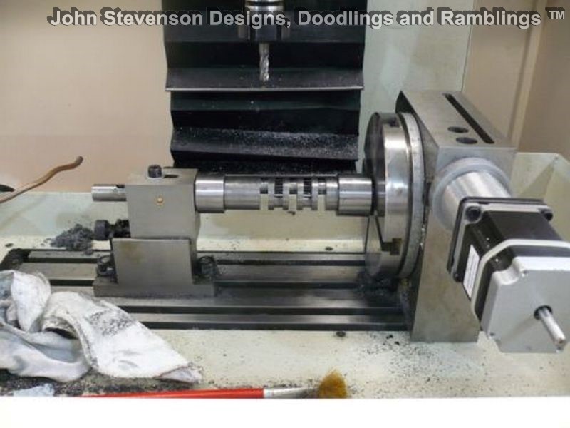 Close up of the finished job. 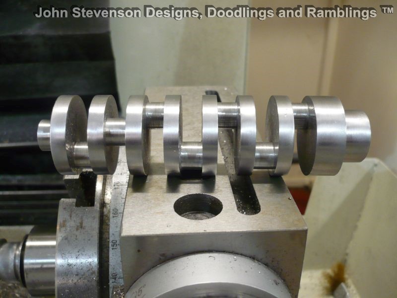 As an idea of size the pin is 10mm diameter and the spacing between webs is 8mm. First 5 journals from the right are at 180 to each other. last two are at 90 degrees as I got fed up with 180 ! John S. |
| NJH | 02/11/2011 19:57:55 |
 2314 forum posts 139 photos | Hi John Now that IS a good use for CNC. I guess you can also get well away from it - just in case it all goes wrong!!  Regards Norman |
| JasonB | 02/11/2011 20:13:50 |
25215 forum posts 3105 photos 1 articles | Posted by Steve Withnell on 02/11/2011 19:16:14:
Hi Jason, is there benefit in annealing after rough turning? My first attempt rang like a bell. Can't do any harm
 J |
| Steve Withnell | 02/11/2011 21:59:31 |
858 forum posts 215 photos | Posted by John Stevenson on 02/11/2011 19:25:11:
We have just been cutting some at the Warwick show on the CNC's as demo pieces.
<snip>
First 5 journals from the right are at 180 to each other. last two are at 90 degrees as I got fed up with 180 !
John S.
First you establish envy, then you rub it in. You bad man.
Looks like a six rotary table on a KX3 - I guess there is ample capacity on a KX1 and a 4 inch table (assuming same size workpiece)?
Steve
|
| John Stevenson | 02/11/2011 23:03:15 |
5068 forum posts 3 photos | Steve, No reason why not if the part will fit in, It's a very forgiving operation as opposed to the standard way of throwing them out on different centres with the knock bang crash associated with it. A lot slower due to the speed of the rotary table but we were still taking 1mm off per pass and it was very quiet in operation. Talking of envy  We did these on the last couple of days at the show. 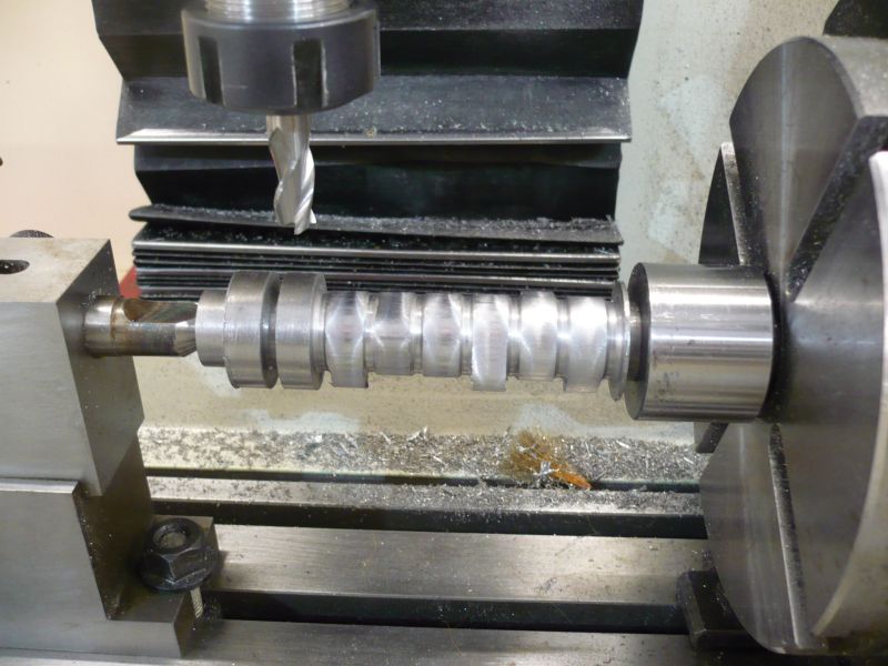 And again the finished job. 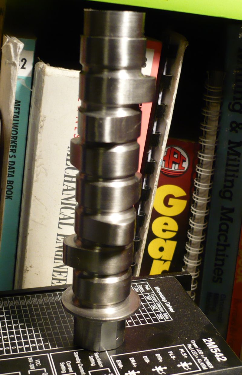 This has been spun in the lathe and a piece of scotchbrite wafted over it, some tool marks are still visible because I didn't want to polish it completely up otherwise you don't get an idea of finish straight off the machine. With a sheet of paper to start with giving you all the offsets of each cam [ instead of winging it and adding numbers in my head ! ] you get a perfect shaft every time. |
| Michael Horner | 03/11/2011 07:51:28 |
| 229 forum posts 63 photos | Hi John
The crank looks fantastic, I have the hardware any chance you will be posting the code
 ? I am building the Whittle V8 and after bending the crank 5 or 6 times in the lathe it got put on the back burner. The dummy ones where made from mild steel which may have been part of the problem, but having not done any engine building before probably contributed as well. ? I am building the Whittle V8 and after bending the crank 5 or 6 times in the lathe it got put on the back burner. The dummy ones where made from mild steel which may have been part of the problem, but having not done any engine building before probably contributed as well.Michael. |
| wotsit | 03/11/2011 16:31:01 |
| 188 forum posts 1 photos | Hasn't this thread gone a bit astray - the initial questions were about building up or machining CRANKSHAFTS, with the difficulties involved, but the later comments refer to CAMSHAFTS - surely a different issue, since usually the throw, involving turning offset pins, is (usually) much less on a camshaft. I don't mean to belittle the efforts needed to make these items, bit it doesn't seem to address the original question(s) - I too have doubts about the longterm advisability of building up crankshafts using adhesives. My own efforts have always been silver soldered and pinned. While on this theme, somewhere I have seen an article about making a crankshaft with offset webs by first making an oversize blank 'in the flat' - it was cut as though all webs were in line from a piece of thick plate, then heated and twisted at each web to get 120 degrees offset (three bearings in this case), then finish turned to size. I'll try and find it later. This is another alternative, but I would guess it could be very difficult to get exact 120 degree relationship between each crankpin, and to keep the whole thing straight, to say nothing about the possible stresses caused by heating and twisting the thing. The CNC work is impressive - perfect for CNC - wish I could afford to do it  |
| Steve Withnell | 03/11/2011 18:03:52 |
858 forum posts 215 photos | If we don't stray it's not much fun and we learn less.
It's one of the disadvantages of Web forums over Usenet groups. Proper Usenet client software allows the discussion to wander all over the place, without disrupting the main theme, each sub thread having it's own following. Funny how an old text based internet app has greater functionality than a new Web app and is massively less resource intensive too.
The web app provides easier access to a wider audience, hmmm.
Sorry, a digression got the better of me!
Steve
|
| Andrew Johnston | 03/11/2011 20:58:14 |
 7061 forum posts 719 photos | Hold tight, never mind astray, we're about to go off-road! Wow, the CNC crankshaft looks great. I think I've understood the toolpath; is it like this sketch, looking along the axis of the crankshaft: 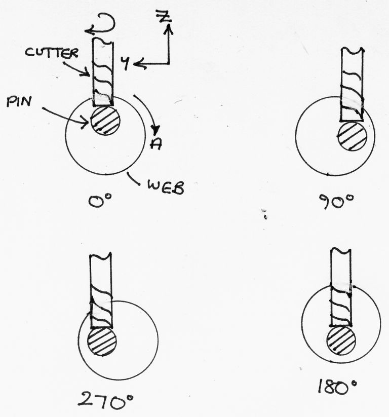 I have two technical questions for John. One, is the repeated G-code a series of G01 moves in Y, Z & A, or is it possible to use G02/G03 in Y & Z with a rotation in A as well? Second, if we assume that the centre cutting endmill is actually ground slightly concave on the end will this result in a barrel shaped pin? I have built a crankshaft for a hit 'n' miss engine using loctite and pinning. However, the engine hasn't run yet, so may be I'm in for a surprise at a later date! Regards, Andrew |
| John Stevenson | 04/11/2011 00:16:40 |
5068 forum posts 3 photos | Andrew, Yes you have it . There is no G Code as such although it does make the moves you say. We looked at using the G19 plane, ie working in Y and Z instead of X and Y but it got very complicated quickly. This is part of the code and is all you see on screen, there is no scrolling of numbers as you are used to seeing but rather two subroutines working behind the scenes. #1=[30] ;BAR #2=[15] ;PCD #3=[10] ;PIN #4=[18] ;Passes #5=[0] ;A #6=[1] ;Pass G0 G21 G49 G40.1 G17 G64 G80 G50 G90 G98 M6 T1 M03 S4000 G00 G43 Z10.0 G00 A0.0 Y0.0 X5 M98 P003 Q#4 A0.00 M5 M9 M30 In the later part of the 'code' it calls a sub routine P003, that works out where the tool is in relation to A and Z. That subroutine in turn calls another subroutine, P004 that works out where the tool is in relation to Y and Z. The whole code is about double what is posted above. At the moment I don't want to release this as it's all the work of small son and I need his permission. Good thing about this is it's all powered by variables set out at the beginning so it will work for any crank throw. The figures in the variables are the ones relating to the crank we cut, 30mm OD, 10mm pin, etc. Good point about the concave cutter, never thought to measure the edges as opposed to the centre, Perhaps we need a small grinder carried by the Z axis so it can go round and do a final clean up ? John S. Edited By John Stevenson on 04/11/2011 00:17:31 |
| Andrew Johnston | 06/11/2011 14:19:55 |
7061 forum posts 719 photos | Hi John, Thanks for the information. Don't worry about posting the G-code, I'm not about to start CNC machining crankshafts. However, it is an interesting technique, which I shall store away for future reference. I tried a quick programming exercise for something similar in my CAM software. It failed miserably, so it looks like hand coding if I need to use the technique. I guess one could ameliorate the 'barrel' shape of the pin by doing some final passes with the cutter offset from the centre of the pin in Y, or alternatively stop every 'n' degrees in A and make a pass of the cutter in Y. Both would improve the shape of the pin but neither would make it a true cylinder. My gut feel is that offsetting the cutter in Y would give an acceptable shape with fewer moves. Regards, Andrew |
| Tony Martyr | 08/11/2011 12:07:50 |
226 forum posts 45 photos | Not having access to a CNC machine centre and having to rely on my trusty Myford I am going to first try a 'pin and locite' fabrication followed by finished machining. I will normalise the steel parts after cutting and see how it goes - at least there will be less swarf
Tony
|
| Richard Parsons | 08/11/2011 13:35:27 |
 645 forum posts 33 photos | Steve rember this http://www.model-engineer.co.uk/forums/postings.asp?th=52543
RDGS
Dick |
| Clive Hartland | 08/11/2011 14:05:50 |
 2929 forum posts 41 photos | The SAAB 95 two stroke engines had a made up crankshaft, they were assembled with discs and the main brgs. were rollor type and the conrod brgs. were rollor type as well, all assembled in one go.
Clive |
| Gordon W | 09/11/2011 10:16:14 |
| 2011 forum posts | Slightly off topic, but related. Has anybody an idea what sort of torque can be transmitted by a glued joint ? I'm thinking say 1" dia x 1" long, steel, fits as required, slow setting adhesive to give time for assembly etc. I've searched all over but can't find anything reliable ( that I can understand) Somebody must have done tests ? |
| Clive Hartland | 09/11/2011 10:21:35 |
2929 forum posts 41 photos | I think that relying purely on a glued joint is not a good thing, A press fit is required where perhaps one part is heated and one cooled and when reaching normal temperature a stable joint is achieved.
I know of two applications I have been inolved with where the cooling/heating method was used. No failure was ever recorded.
Glue and a mechanical fix after is best for this method which makes it easy to make and assemble.
Clive
|
Please login to post a reply.
Magazine Locator
Want the latest issue of Model Engineer or Model Engineers' Workshop? Use our magazine locator links to find your nearest stockist!
Sign up to our Newsletter
Sign up to our newsletter and get a free digital issue.
You can unsubscribe at anytime. View our privacy policy at www.mortons.co.uk/privacy
Latest Forum Posts
- *Oct 2023: FORUM MIGRATION TIMELINE*
05/10/2023 07:57:11 - Making ER11 collet chuck
05/10/2023 07:56:24 - What did you do today? 2023
05/10/2023 07:25:01 - Orrery
05/10/2023 06:00:41 - Wera hand-tools
05/10/2023 05:47:07 - New member
05/10/2023 04:40:11 - Problems with external pot on at1 vfd
05/10/2023 00:06:32 - Drain plug
04/10/2023 23:36:17 - digi phase converter for 10 machines.....
04/10/2023 23:13:48 - Winter Storage Of Locomotives
04/10/2023 21:02:11 - More Latest Posts...
- View All Topics
Support Our Partners


Shopping Partners
Subscription Offer

Latest "For Sale" Ads
- Reeves** - Rebuilt Royal Scot by Martin Evans
by John Broughton
£300.00 - BRITANNIA 5" GAUGE James Perrier
by Jon Seabright 1
£2,500.00 - Drill Grinder - for restoration
by Nigel Graham 2
£0.00 - WARCO WM18 MILLING MACHINE
by Alex Chudley
£1,200.00 - MYFORD SUPER 7 LATHE
by Alex Chudley
£2,000.00 - More "For Sale" Ads...
Latest "Wanted" Ads
- D1-3 backplate
by Michael Horley
Price Not Specified - fixed steady for a Colchester bantam mark1 800
by George Jervis
Price Not Specified - lbsc pansy
by JACK SIDEBOTHAM
Price Not Specified - Pratt Burnerd multifit chuck key.
by Tim Riome
Price Not Specified - BANDSAW BLADE WELDER
by HUGH
Price Not Specified - More "Wanted" Ads...
Get In Touch!
Do you want to contact the Model Engineer and Model Engineers' Workshop team?
You can contact us by phone, mail or email about the magazines including becoming a contributor, submitting reader's letters or making queries about articles. You can also get in touch about this website, advertising or other general issues.
Click THIS LINK for full contact details.
For subscription issues please see THIS LINK.
Digital Back Issues


Donate

 Register
 Log-in
Model Engineer Magazine
- Percival Marshall
- M.E. History
- LittleLEC
- M.E. Clock

ME Workshop
- An Adcock
- & Shipley
- Horizontal
- Mill

Subscribe Now
- Great savings
- Delivered to your door

Pre-order your copy!
- Delivered to your doorstep!
- Free UK delivery!
All Forum Topics > Beginners questions > Crankshaft construction