Forum sponsored by:

Machining very thin materials
| Luc Belanger | 02/10/2011 00:08:28 |
| 5 forum posts | Hello all.... This is my first post. What is getting me in this hobby is not engines per se, though I am going to build one or another one of these days for the grandsons!! My main interest is audio devices construction, especially the microphones. The first project I want to tackle, once I learn machining basics, is based on this article here: Stereo microphone As you will see if you read the article, condenser type microphones, or any other types, are very very finicky devilish devices! The details are even more important than the basics!! Based on this article, and others, I will need for my own designs fabricating machined spacers with very thin ( .001'') brass or stainless steel spacers. These spacers are simple rings of say .150'' rim width, about 1'' diameter with some equidistant holes around the rim and .001' thickness. How do I go about fabricating these? Right away, using a punch and die set is a bit out of question since I can not have any burr whatsoever. The parts have to be perfectly flat with sharp edges, unless someone can provide me with a method of deburring the edges, mainly the innard one. I have considered having these parts made with a laser cutting machine but it adds quite a bit to the cost of the final capsule. Thanks, Luc |
| Ed Duffner | 02/10/2011 01:50:12 |
| 863 forum posts 104 photos | Hi Luc,
I am also new to machine basics (and model engineering). A possible solution could be to make a multi hole press and dye, like a miniature fly press to make all of the holes at once and then surface grind the parts to remove any burr. Other than that maybe a dividing head would work and mill each hole, if you can get a cutter or center drill the correct diameter.
Could these be made from non-metallic material and moulded to the exact shape?
Kind regards,
Ed. |
| Luc Belanger | 02/10/2011 03:46:14 |
| 5 forum posts | Actualy my question is a bit more 'insidious' I will also need shims made of teflon or other high dielectric materials I have not researched as of yet. I thought of making 'sandwiches' of a base plate, say .125, many layers of shim material, another 'slice' of .125 material and machine the whole thing as if it was a single thick piece.... say .350'' or so.... My concern is about preventing tear ups of the thin material. Since this is not a commercial venture, cost efficiency is not the prime axiom here..... within reason. Brass material is very expansive here in Québec! And not that easy to find in small quantities. Luc |
| JasonB | 02/10/2011 07:26:33 |
 25215 forum posts 3105 photos 1 articles | I would have thought the sandwich method would be your best bet. The 0.001" shim stock can be cut into say 1.125" squares and temporary clamped together with some 1/8" outer plates while you drill each corner for a nut & bolt.
Once the sandwich is bolted up drill all the holes, then make up a mandrel for the lathe that will fit the central hole with a threaded end for a nut & bolt. Bolt the sanwich onto the mandrel and light cuts to get the outer edge round.
J |
| ady | 02/10/2011 07:53:50 |
| 612 forum posts 50 photos | Sounds like the kind of work they used to do on pultra micro lathes. |
| Bogstandard | 02/10/2011 09:17:12 |
| 263 forum posts | I suppose you could easily modify this method to get your discs to size, just trap the discs together between two end plates, and then machine the whole lot, including end plates, to the diameter you require. John |
| Ian S C | 02/10/2011 11:23:31 |
 7468 forum posts 230 photos | I used Johns method to make the laminations for an elecric motor armature, left it in the chuck and transfered it all to the mill and cut the slots for he windings through the 1/4" end plates.
The hole in the spacers could be bored. After the OD is completed, a blind tube that the discs fit in is made with a cap that screws on to hold the discs firmly in place. The discs all ready have a undersize hole, and its easy enough to mount the tube in the chuck an bore it to size with a sharp tool. Not too sure about the holes around the rim, they sound like a punch job. Ian S C |
| maurice bennie | 02/10/2011 12:13:56 |
| 164 forum posts 1 photos | Hi Luc, How about photo etching ,I have used this way of cutting but it does leave a bit of a rough edge but no distortion of the metal.
Good luck Maurice.
|
| Billy Mills | 02/10/2011 12:48:23 |
| 377 forum posts | The article must be around 40-50 years old, it reflects ancient methods. The clamp rings that clamp the mylar to the capsule body can be etched from brass or copper using ferric chloride as the etchant however there is NO requirement for them to be a thou thick, they could be readily made from thicker material that is stack drilled with sacrificial material above and below as already described. There is NO need for insulating spacers, that is done by the perspex outer rim.
The article glosses over the film tension issue, high film tension is a very important part as are the holes in the back plate. Many commercial microphones have the film glued to a ring. After curing a second ring is forced inside the first ring to tension the film then the film is glued to the backplate assembly. When cured the excess film is trimmed off and the edges trapped under another ring forced over the backplate assembly, no screws through the film are needed or desirable. The ring becomes the front electrode connection. Currently back electrodes with holes and the spacing rim are normally cast or moulded then the inner part of the back electrode is coated with evaporated aluminium or gold.
Most modern capacitor microphones use electrets in the back electrode to avoid the need for the polarising voltage. However the quietest microphones around use a very different method which was glossed over, the capsule is used to tune a discriminator which is driven by a crystal oscillator.
The high polarising voltage -100V- is applied over a gap of 0.0015" . This requires extreme care and ultra clean degreased parts to avoid insulation failure. Commercial microphones of this type are made in "clean rooms". Not an easy home project.
Best of good machining luck,
Billy.
PS don't bother with valves, use fets or suitable opamps.
|
| Luc Belanger | 02/10/2011 15:33:24 |
| 5 forum posts | Thanks for all these advices. I did come with the conclusion that stack machining was the way to go, but the collective wisdom here is much more than my own, so checking here made sense. Not to start a thread within a thread, and to give a bit of background on myself, I am 58, I have been a musician and sound engineer since I am about 12 years old and I really know my way in electronics being studio maintenance engineer and industrial machinery builder/programmer/designer. But as Billy has stated, this is not an easy project. The rings I need are not for the construction of the capsules in the articles, but for other design I want to try. They will be used as spacers between the two half capsules creating a resonant cavity there helping o tune the whole affair. Microphone capsules design and fabrication is very complex, I actually do not think I will succeed at achieving what I want, but being stubborn (or idiot, depending who you talk to) I will give it a shot anyway. It is just time invested, material cost is rather minimal. Luc |
| Billy Mills | 02/10/2011 17:19:15 |
| 377 forum posts | You can cut thin plastics with a very sharp punch against a hard rubber pad, with a lathe the punch is a simple cylinder with the sharpest corner you can get. You can elaborate by turning a knife edge or use a sharpened thin wall tube to make small holes. Even a Knife used with a washer template will give a good edge.
I would not agree that capacitor microphones are difficult to build or design, they are the simplest microphones possible, the theory and practice could not be much simpler, it is just that manufacturers keep their exact processes under their hats and very few homebrew designs have ever been published. With care and some time Luc will get there.
Billy.
|
| Luc Belanger | 02/10/2011 21:22:43 |
| 5 forum posts | Billy said: ''I would not agree that capacitor microphones are difficult to build or design, they are the simplest microphones possible, the theory and practice could not be much simpler'' I agree the principles' are very simple. I disagree, the execution is very difficult because of the very exacting tolerances required. The maths behind the design of a capsule are unknown to me. Probably not too complex, but I do not know where to look for it. The principle is to have a volume of air trapped behind the diaphragm with a tightly controlled elastic behaviour, The pattern of holes of different sizes and depths, with some that goes trough, is where the designer can decide of the sound ultimately delivered by the capsule. There are other factors involved also in the design of the body, the electronics etc. It is not a simple project indeed! And by the way, the simplest microphone design is the ribbon. It is simply a corrugated aluminium foil about 4 micron thick, 6X30mm or so, lightly tensioned in the fieldgap of a strong magnet. The distance between the ribbon and the throat of the magnet is about 1 or 2 micron, without touching... Electrically wise, a simple 1:30 transformer is used to carry the signal out. Now THAT is simple!! Luc |
| Sam Stones | 02/10/2011 23:58:35 |
 922 forum posts 332 photos | Hi Luc,
You might consider using wire cutting, which is a very neat EDM process. This was a method I elected to contract out for some thin stainless steel electrodes. The cost here in Melbourne, was quite low especially when compared with making up a stamping tool.
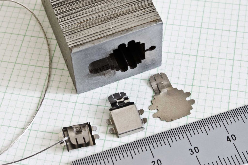
Each shim measured about 25mm x 20mm, and I sandwiched them between a couple of pieces of gauge steel before rivetting them together with two silver steel dowels which passed through the whole assembly. The contractor surface ground a couple of faces of the block for reference.
The row of electrodes (right to left) show an initial blank, a formed electrode, and my method of attaching the wire.
Because the shims were tightly sandwiched together, you can see that the edges are very `clean'. For reference, the small squares on the graph paper are 2mm. Although it is about ten years ago or more, and my memory is not as sharp, please feel free to ask, if you think I can help further.
Best regards,
Sam |
| Billy Mills | 03/10/2011 02:03:05 |
| 377 forum posts | Luc
You will find good descriptions of basic design principles in most good works on acoustics however I had the advantage of working for an offshoot of a German manufacturer after graduating so I am very aware of the way that capacitor and dynamic microphones are designed, tested, manufactured and serviced. I was involved in evaluating different designs and in designing test instrumentation so have a little background in the subject.
You are the first person that I have ever met that thinks that a ribbon is simpler than a capacitor microphone. The tolerances in the capacitor microphone are no great shakes, you are talking about a simple single step of a few thou, there is no difficulty at all in cutting this step, if it was +/- 10% it would have around 1dB impact on sensitivity. Some of the best units have a cast ceramic body with a cast in rim, this is rubbed down on 1000 grit wet and dry in manufacturing to get the spacing standardised. The hole pattern is no black art, a regular pattern of about 50-100 holes with around 20- 40% of the backplate area works well. If the holes go all the way through you have bidirectionality, closed off you have omni, with some all through and some stealth, wideband cardiod.
If you make a metal backplate then a quick acid dip will etch out micro burrs because they have a very big surface area /volume ratio. It is also very good to use a real ultrasonic cleaner before assembly. Give it a go.
Billy.
|
| Luc Belanger | 04/10/2011 02:28:55 |
| 5 forum posts | Thank you so much Billy!  Now you gave me in a few sentences much to ponder and experiment with! Now all I need is to receive My machines ordered last late June!! just a couple more weeks as I am told.... Boy are those Chinese boats ever so slow!!  Luc |
Please login to post a reply.
Magazine Locator
Want the latest issue of Model Engineer or Model Engineers' Workshop? Use our magazine locator links to find your nearest stockist!
Sign up to our Newsletter
Sign up to our newsletter and get a free digital issue.
You can unsubscribe at anytime. View our privacy policy at www.mortons.co.uk/privacy
Latest Forum Posts
- *Oct 2023: FORUM MIGRATION TIMELINE*
05/10/2023 07:57:11 - Making ER11 collet chuck
05/10/2023 07:56:24 - What did you do today? 2023
05/10/2023 07:25:01 - Orrery
05/10/2023 06:00:41 - Wera hand-tools
05/10/2023 05:47:07 - New member
05/10/2023 04:40:11 - Problems with external pot on at1 vfd
05/10/2023 00:06:32 - Drain plug
04/10/2023 23:36:17 - digi phase converter for 10 machines.....
04/10/2023 23:13:48 - Winter Storage Of Locomotives
04/10/2023 21:02:11 - More Latest Posts...
- View All Topics
Support Our Partners


Shopping Partners
Subscription Offer

Latest "For Sale" Ads
- Reeves** - Rebuilt Royal Scot by Martin Evans
by John Broughton
£300.00 - BRITANNIA 5" GAUGE James Perrier
by Jon Seabright 1
£2,500.00 - Drill Grinder - for restoration
by Nigel Graham 2
£0.00 - WARCO WM18 MILLING MACHINE
by Alex Chudley
£1,200.00 - MYFORD SUPER 7 LATHE
by Alex Chudley
£2,000.00 - More "For Sale" Ads...
Latest "Wanted" Ads
- D1-3 backplate
by Michael Horley
Price Not Specified - fixed steady for a Colchester bantam mark1 800
by George Jervis
Price Not Specified - lbsc pansy
by JACK SIDEBOTHAM
Price Not Specified - Pratt Burnerd multifit chuck key.
by Tim Riome
Price Not Specified - BANDSAW BLADE WELDER
by HUGH
Price Not Specified - More "Wanted" Ads...
Get In Touch!
Do you want to contact the Model Engineer and Model Engineers' Workshop team?
You can contact us by phone, mail or email about the magazines including becoming a contributor, submitting reader's letters or making queries about articles. You can also get in touch about this website, advertising or other general issues.
Click THIS LINK for full contact details.
For subscription issues please see THIS LINK.
Digital Back Issues


Donate

 Register
 Log-in
Model Engineer Magazine
- Percival Marshall
- M.E. History
- LittleLEC
- M.E. Clock

ME Workshop
- An Adcock
- & Shipley
- Horizontal
- Mill

Subscribe Now
- Great savings
- Delivered to your door

Pre-order your copy!
- Delivered to your doorstep!
- Free UK delivery!
All Forum Topics > Beginners questions > Machining very thin materials