Forum sponsored by:

Parting off on Myford lathes
| John Stevenson | 16/01/2011 14:10:31 |
 5068 forum posts 3 photos | So a gear head lathe can part off with no chatter at all ? Sorry you have quoted YOUR interpretation of the problem. Give 10 people a Myford lathe, the same material, same tooling and all 10 will have different problems - fact of life. What works for one does not mean it works for all. John S. |
| KWIL | 16/01/2011 14:25:48 |
| 3681 forum posts 70 photos | I agree with John S, I have Myford S7 with the correct belt tension, I never use a rear parting tool, ( I do have one but it lies totally unused). I always use a front plain Eclipse blade or a Q Cut, both mounted on Dixon QC toolholders and do not have a real problem, I also have a M300 Harrison which is a gear head and treat it the same. Keep it sharp, keep it at the correct height and the speed for the material being cut, if you experience a lot of chatter, it could well be you. Edited By KWIL on 16/01/2011 14:27:47 |
| Chris Trice | 16/01/2011 14:27:41 |
 1376 forum posts 10 photos | Unimat SL lathes and their 'rubber band' belts are prone to chatter when turning normally. However, surely the much heavier mass of a chunky chuck on a larger lathe resists changes of rotational speed on the frequency it would have to. It would be easy to test by waiting until you get chatter parting off and then substitute a larger (4 jaw for example) chuck and repeating the set up. Or, substitute your topslide for a solid toolholder bolted directly to the cross slide but still sited the right way up and the chances are, no more chatter. Again, why wouldn't you get chatter when cutting conventionally with Myford belts if the belts had a springing issue? What is about parting off that makes it different? It's just a large heavy cut and you get chatter under those circumstances with a conventional tool which we know can be cured by increasing the rigidity of the tool/workpiece set up. Maybe it's a contributory factor but spring in the tool holding set up just strikes me personally as a far more likely culprit. |
| John Haine | 16/01/2011 16:18:11 |
| 5563 forum posts 322 photos | I use a rear toolpost of the type Kirjeng sell. Blade is ground with a small hollow in the top surface made with a rat-tail diamond file. I follow the advice of GH Thomas, run the lathe reasonably fast so the cut per rev is under better control. I always use power feed (now the lathe is CNC'd there's no alternative). Never have a problem. Also have Q-cut tool which is good but now seldom used, but was used in the Dickson toolholder on topslide. Again used power feed but less good 'cos being a carbide tip the edge is lee keen so needs more cutting pressure. |
| mick | 16/01/2011 16:46:11 |
| 421 forum posts 49 photos | Having spent over forty years in the trade, my experience of parting problems on any style of lathe is down to the nut on the end of the handle. Clean and trouble free parting comes with experience, it realy dosn't matter how many books you read on the subject. The best position for a parting blade is in a rear mounted tool post, perhaps thats why capstan and auto lathes( which were developed over the past hundred years or so) always have the parting blade in such a tool post. |
| Nicholas Farr | 16/01/2011 17:38:08 |
 3988 forum posts 1799 photos | Hi,
I don't believe belt drives cause chatter in the way that has been portrayed in the OP, that is unless you have cheap stretchy belts. I can't imagine Myfords design with cheap belts in mind.
Although there is some elasticity in the belt itself, that doesn't make them stretchy. When belts are correctly adjusted and are driving, this elasticity is largely taken up by the whole system. Any oscillations within the design load, be it heavy or otherwise will be negligible. Belt drives are really good at self balancing to give a very reasonable smooth transmission. Very heavy loads can cause distorsions in the machine itself, making it look as if the belts are stretchy. Over tightening drive belts can cause thier own problems, including distorsion of the headstock spindle, the bearings and the motor shaft, as well as not allowing the drive system to flex within its design.
Every machine has load limitaions, and you should work within them. Chatter can happen in machines that are directly driven, that is with no belts transfering the power.
Regards Nick. Edited By Nicholas Farr on 16/01/2011 17:41:28 |
| John Olsen | 16/01/2011 18:52:30 |
| 1294 forum posts 108 photos 1 articles | In my experience the biggest factor in determining success or failure in parting on the Myford is the width of the parting blade. A narrow blade is better than a wide one, up to the limit of what the narrow blade can do in the way of depth of course. The Myford is not a particularly heavily built machine, and the same sort of thing applies with form tools, it will chatter with wide ones. While the belts are possibly a factor, the general lack of rigidity is probably more important. Of course there is nothing to stop somone converting a Myford to gear drive to see if it makes a difference. I used to use a very narrow parting blade, ground from square HSS on my Unimat, that one was just a little over 1mm wide, and was good for up to 19mm diameter. regards John |
| Laurence B | 16/01/2011 21:32:30 |
| 58 forum posts | Having used a Myford S7 for a few years I've never had any problems with parting off.
I've always understood that successful parting off depends on as rigid a tool set up as possible with minimum overhang of the tool,the correct feed and the correct rotational speed.I've never really thought about the belt tension,which is about correct to the manufacturers recommendations,even though the drive belts invariably have oil on them! |
| Terryd | 16/01/2011 22:12:00 |
 1946 forum posts 179 photos | Hi michael, The issue of parting off with Myfords (and probably other small lathes) is well covered on the Myfords website here. Their theory coincides with my own except the position of the rotation centre of the front mounted toolpost but that's another story. I also have an extension of the idea due to the forces involved and a little analysis will make clear my ideas. I hope. I apologise for the length of the post and hope that it is not too boring. Every lathe has some play in the headstock bearings, no matter how little, it is there, and there will be some flexibility in the tool (absolute rigidity is impossible) as well as some flexibility in the workpiece, metal unfortunately is flexible. it may be minute movement but the effects of all these are cumulative. As I see it, the front mounted tool will tend to be forced downwards while the work is trying to climb the tool. Even if the tool is set exactly on centre before parting these effects will tend to force the tool below centre as the work progresses. There will then be a forward component to the forces acting on the tool pulling it into the work and the backlash present will allow the tool to tend to move forward, into the workpiece. As the diameter of the workpiece decreases the forward pull increases as does the tendency of the work to climb and the tool to be forced down. Eventually the tool tries to submarine below the work into a restricted space between the work and the cross slide. It jams, causes problems and then the 'bang' we have all dreaded, a broken tool and possibly damaged workpiece as a consequence.. That is why large diameter work such a 100mm dia tubing etc is relatively easy to part off, because these effects are minimised at the larger diameter, it is as the cut progresses and the work gets smaller that the effect increases. I.e. the smaller the diameter the greater tendency to climb and the forward, pulling force acting on the tool increases and the tool submarines. With a rear toolpost as the flexibility allows the tool to be forced upwards it is pushed away from the work due to the position of the centre of rotation of the toolpost. hence less jamming. It is also mounted directly onto the cross slide and not on the compound and the latter allows more movement due to the two sets of dovetails. If you have difficulty visualising, imagine a 100mm cube of wood as a toolpost, knock in a nail towards the top of one side so that 20 mm are protruding to represent the tool, and then press down on the end of the nail and imagine the movement, this is the action of the front toolpost, now lift the nail at the end and this is the action of the rear toolpost. Both are greatly magnified of course, but it doesn't take much imagination to understand the consequences of these movements. This is basically similar to the analysis of G H Thomas with some of my own observations and analysis added, I look forward to sensible debate and comments on these ideas. Terry Edited By Terryd on 16/01/2011 22:20:43 |
| Nobby | 16/01/2011 23:43:12 |
 587 forum posts 113 photos | Hi
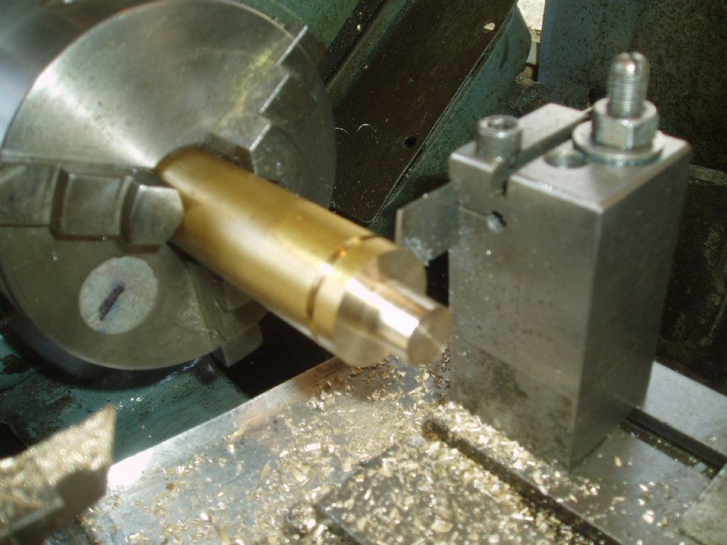
As a lad I worked on a ward 2a capstan .parting from the back . the lads on the lathes sometmes used to borrow my M/C to part of some of there components.Please see photo parting 1&1/4 brass on my myford S7 MK1 as Terry d suggests the post is direct on the crossslide . As you can see Its quite away out of the chuck but it parted off fine
Regards Nobby
 |
| John Stevenson | 17/01/2011 00:29:35 |
5068 forum posts 3 photos | Not really a fair test Nobby in brass, you could do this with a butter knife and have no trouble. I regularly part off 3" brass with a front tool and the only problem I have is the lathe won't run fast enough or feed fast enough. Has anyone used one of those parting tools that has a support above the blade that you set to rub on the top of the work ? Seen them in old textbooks and they have been covered in past copies of ME. Never used one but I would imagine that they help support the blade from trying to nose dive and dig in. Present job at the moment is making a batch of gear blanks out of EN36, 30mm diameter with a 15mm centre hole. Making these in sticks 15" long, drilled from either end then reamed from either end and parted off. I have about 4" or 5 " sticking out the chuck and support with the revolving centre which according to many is a no no. However now done well over 500 -700 of these over the last 2 - 3 years with no problems. As you break thru instead of it jamming like many think the cut blank just tips to one side, stop, remove and set for the next blank. Even on a robust industrial lathe this makes all the difference to smoothness of cut and no chatter. 3/32 " HSS steel blade in front toolpost, no back post on this machine, I only use HSS because I have loads of blades so tooling costs are zero. John S. |
| Chris Trice | 17/01/2011 10:30:56 |
1376 forum posts 10 photos | Arguably, if you're turning by hand, are the belts the cause or just emphasise showing the resultant judder? Do you still get chatter at the same settings if the belts are slackened? |
| blowlamp | 17/01/2011 10:39:19 |
 1885 forum posts 111 photos | I'm struggling with some of the logic of the 'elastic' drive belt theory in this thread.
Anyone that's ever tried to stretch one of these belts will know that they've got virtually no give in them at all, let alone be elastic.
They are after all reinforced with various types of cord to prevent this.
It also would be interesting to know if this theory for a Myford holds true whilst utilising it's back-gear.
I have a geared-head head lathe that is belt driven from the motor and am intrigued to know if the theory predicts that it also will be subject to the problem, particularly when geared at a similar motor speed / headstock speed ratio to that of the Myford when parting off.
As has been pointed out in the other thread on this, it's either deflections in the tool/workpiece interface and/or chip crowding in the groove being cut.
My view is that chip crowding is the main culprit as it's quite unusual to get a lock-up in the early stages of the cut, while the groove is still shallow.
Martin. |
| Dusty | 17/01/2011 11:38:03 |
| 498 forum posts 9 photos | Michael
Turning by hand! with the best will in the world you are not going to get a smooth power transition to the workpiece, you might think it is smooth but it will not be. You have started your judder, you are going downhill from that moment on. |
| chris stephens | 17/01/2011 13:09:48 |
| 1049 forum posts 1 photos | Hi Guys,
Does anybody else think that the pivot points in the Myford drawing are in the wrong place, leading to a false assumption about dig-ins. I know that this drawing, and rear mounted tooling, are often shown as being the definitive answer but I have my doubts. Why not assume that the pivot point is actually at the point that the blade exits the post, after all the blade is a lot less stiff than the post. If we do assume the new pivot point is at the toolpost, it would completely negate the reasoning for the "benefits" of a rear mounted tool.
Are there any QUALIFIED structural engineers out there who could give chapter and verse, and not trot out the hackneyed old tat. I am waiting to be convinced, and like others I would like to see reasoned, scientific and definitive answers.
I do see that there is an element of faith healing in rear mounted parting, like a placebo, if you think it will work it often does but this is not a good enough argument for its universal adoption. The converse might however be true. If you have experienced dig-ins, through inexperience, while using a front mounted tool, you might well have this in the back of your mind and be a little timid, where confidence might have got you through!
Over to you Guys,
chriStephens
|
| Terryd | 17/01/2011 14:09:32 |
1946 forum posts 179 photos | Hi Chris stephens, I qualified as a structural engineer following my apprenticeship and degree. And I then worked for several years in that area so I do have some expertise. If you wish for confirmation I will scan my apprentice debentures and degree certificates for you. I do not rework what you call 'old tat' and my personal analysis is based on many rears theoretical and empirical experience. I don't agree with your analysis of the centre of rotation of the tools but even so it would certainly not "negate the reasoning for the "benefits" of a rear mounted tool." I would maintain that what you call 'dig in' is caused by the front mounted tool trying to submarine below the workpiece into an ever decreasing space below the work. The forward component of the force imparted by the workpiece as the tool submarines will pull the tool forward thus increasing the effect until it jams This can be shown by a simple and straightforward vector analysis and as the diameter of the work decreases the forward (Pulling) force into the backlash will increase, which explains to some extent why larger diameter work does not cause many problems as I originally suggested. The rotation at the rear lifts the tool and the centre of rotation you propose will still tend to move the tool away from the work as it rises as in the Myford analysis and there is no restricted space to constrict it. A simple geometrical exercise with compasses and paper will prove that. I welcome your contribution to the debate about points of rotation, but using emotive and derogatory remarks and implied insults in your use of capitals does your argument no good at all. As Michael asked for in his original post he would like a debate by "reasoning and proper discussion," much of your message does not fall into that category. Regards, Terry |
| blowlamp | 17/01/2011 14:40:13 |
1885 forum posts 111 photos | Those drawings are put together in such a way as to reinforce the argument of the author.
To my way of thinking - and this is assuming that both the tool and toolpost are up to the job - then the pivot point should actually be at the front foot of the toolpost on the left, which is almost directly under the tip of the cutting tool.
In that position though, there is so little extension of the tool beyond it's support footprint, that there is practically no opportunity for a rocking movement to happen due to a downward force on the tool.
Non of the above helps the assertion of the rear toolpost being stiffer, as the strength of the tee-slot mounts must also called be called into question when evaluating it's merits.
Anyone with a Gibralter type toolpost should be able to verify that deflection is minimal when parting-off and thus do so with few problems, provided the groove can be reliably cleared of swarf. If a jam-up still occurs with a Gibralter - but not with the same tool mounted at the rear - then I'm pretty sure it's chip crowding.
All the above assumes a lathe in good condition.
Martin. |
| Chris Trice | 17/01/2011 15:45:22 |
1376 forum posts 10 photos | The other thing to consider is workpiece deflection. Not just the workpiece but chuck displacement too. Since the problem gets worse the further from the chuck you are, use of a tailstock centre when the problem occurs is an easy way to discount flexibility and slop in the spindle/bearing/chuck/workpiece should the problem then go away. Trying to understand all the theory is good but testing, as with all experimentation, leads to a set of results from which to draw a conclusion. |
| mick | 17/01/2011 17:20:56 |
| 421 forum posts 49 photos | Call me old fashioned, but I really don't understand how you can work out what's occuring during a machining operation by turning the spindle by hand a feeding a tool into the work piece. In the real world that I use to inhabit, as long as all obvious precautions have been taken, chatter and vibration could be cured by INCREASING, rather than decreasing the speed and feed. Another method is to use a presure pad supported by a live centre. If the job being parted has a bore, then even better and support with a bell centre. I use these methods all the time on my Myford ML7. In the quest for better machining, I know industrial practicies can't always successufully be transfered to the hobby workshop, but they have to be a better place to start. |
| KWIL | 17/01/2011 18:53:03 |
| 3681 forum posts 70 photos | One question, what clearance have you set on the front conical bearing? |
Please login to post a reply.
Magazine Locator
Want the latest issue of Model Engineer or Model Engineers' Workshop? Use our magazine locator links to find your nearest stockist!
Sign up to our Newsletter
Sign up to our newsletter and get a free digital issue.
You can unsubscribe at anytime. View our privacy policy at www.mortons.co.uk/privacy
Latest Forum Posts
- *Oct 2023: FORUM MIGRATION TIMELINE*
05/10/2023 07:57:11 - Making ER11 collet chuck
05/10/2023 07:56:24 - What did you do today? 2023
05/10/2023 07:25:01 - Orrery
05/10/2023 06:00:41 - Wera hand-tools
05/10/2023 05:47:07 - New member
05/10/2023 04:40:11 - Problems with external pot on at1 vfd
05/10/2023 00:06:32 - Drain plug
04/10/2023 23:36:17 - digi phase converter for 10 machines.....
04/10/2023 23:13:48 - Winter Storage Of Locomotives
04/10/2023 21:02:11 - More Latest Posts...
- View All Topics
Support Our Partners


Shopping Partners
Subscription Offer

Latest "For Sale" Ads
- Reeves** - Rebuilt Royal Scot by Martin Evans
by John Broughton
£300.00 - BRITANNIA 5" GAUGE James Perrier
by Jon Seabright 1
£2,500.00 - Drill Grinder - for restoration
by Nigel Graham 2
£0.00 - WARCO WM18 MILLING MACHINE
by Alex Chudley
£1,200.00 - MYFORD SUPER 7 LATHE
by Alex Chudley
£2,000.00 - More "For Sale" Ads...
Latest "Wanted" Ads
- D1-3 backplate
by Michael Horley
Price Not Specified - fixed steady for a Colchester bantam mark1 800
by George Jervis
Price Not Specified - lbsc pansy
by JACK SIDEBOTHAM
Price Not Specified - Pratt Burnerd multifit chuck key.
by Tim Riome
Price Not Specified - BANDSAW BLADE WELDER
by HUGH
Price Not Specified - More "Wanted" Ads...
Get In Touch!
Do you want to contact the Model Engineer and Model Engineers' Workshop team?
You can contact us by phone, mail or email about the magazines including becoming a contributor, submitting reader's letters or making queries about articles. You can also get in touch about this website, advertising or other general issues.
Click THIS LINK for full contact details.
For subscription issues please see THIS LINK.
Digital Back Issues


Donate

 Register
 Log-in
Model Engineer Magazine
- Percival Marshall
- M.E. History
- LittleLEC
- M.E. Clock

ME Workshop
- An Adcock
- & Shipley
- Horizontal
- Mill

Subscribe Now
- Great savings
- Delivered to your door

Pre-order your copy!
- Delivered to your doorstep!
- Free UK delivery!
All Forum Topics > Manual machine tools > Parting off on Myford lathes