Forum sponsored by:

Pprojecting a circle onto a boiler barrel
| Vincent Shaw-Morton | 07/12/2010 21:03:41 |
| 17 forum posts 15 photos |
Hi everyone,
I've started on my first loco and have just finished flanging all the boiler plates, and I'm quite pleased with the results. Anyway on looking at the dome bush I can't for the life of me figure out how to project the cylinder diameter of the bush, ( a circle of course) down onto the boiler barrel. Simply scribing a circle on the barrel with a compass will of course distort the circle. How do people approach this (what appears to be simple) but for me baffling problem?
thanks
Vincent
Edited By Vincent Shaw-Morton on 07/12/2010 21:05:27 Edited By Vincent Shaw-Morton on 07/12/2010 21:05:53 Edited By Vincent Shaw-Morton on 07/12/2010 21:06:26 |
| Weldsol | 07/12/2010 21:10:32 |
| 74 forum posts | H i Vincent
I normally set the barrel on the mill (having alreadt marked the centre) then hole saw followed up with the boring head.
Paul |
| JasonB | 08/12/2010 07:24:41 |
 25215 forum posts 3105 photos 1 articles | Did this quite early on at school technical drawing, its refered to a circle development. Its quite easy to do on a bit of paper with a simple drawing board, maybe search the net as its not easy to explain in words.
But as said above if you can set it up someway to bore on a machine then its easy.
Jason |
| John Olsen | 08/12/2010 08:48:20 |
| 1294 forum posts 108 photos 1 articles | I suspect we are making this a lot more complex than it really needs to be. The "circle" drawn with the compass will be the right size fore and aft, and will be under size at either side. So, assuming a minimum of tooling, eg no boring head or whatever, we mark out the hole with the compass, chain drill carefully just inside and then clean up with a file. Try the bush and file away where needed until the bush is a nice fit. Silver solder is better if the fit is not too snug, 2 or 3 thou clearance is good. regards John |
| Les Jones 1 | 08/12/2010 09:21:25 |
| 2292 forum posts 159 photos | Hi Vincent, You could make a tool similar to the hole cutters that Toolstation sell but with just one blade sharpened as a scriber. To see a picture of the hole cutter on Toolstation's website enter "hole cutter" in the search box. If you drill a pilot hole and mount the mount the tool in a pillar drill or some kind of guide you can let it move up and down to keep the scriber in contact with the surface as it is rotated. I used this method to cut a hole for the burner in a furnace that I was making. For that the scriber had to be quite long at the hole was tangential. I was cutting a hole about 2.5" dia. in a cylinder of about 13" dia. It has just occurred to me that if you use two blades then keeping both blades in contact with the surface would remove the need for a guide IF the axis of the hole being cut goes through the centre of the main cylinder. Les |
| KWIL | 08/12/2010 10:20:22 |
| 3681 forum posts 70 photos | If you look in My Album, you will see a FC3 3 flute throwaway cutter making the holes in a boiler barrel by chain milling [like chain drilling but you can do it on a curved surface]. Once done this way, you can open it out to exact size by use of a boring tool. Edited By KWIL on 08/12/2010 10:21:34 |
| Ian S C | 08/12/2010 11:27:47 |
 7468 forum posts 230 photos | I needed two 0ne inch holes in the side of a piece of two inch copper pipe, so I made a one inch hole saw. Heated an inner race from a ball race of suitable size,welded a shaft with a flange onto the peice that was to be the cutter, put it in the lathe and took it down to 1" dia, then filed some teeth on it, then rehardened it, it worked well and has since been used on steel. I had tried drilling and fileing, but mucked it up.isc |
| Clive Farrar | 08/12/2010 15:15:15 |
 125 forum posts 41 photos | There are two ways of doing it. on the centre line of the boiler where you want the flange to go mark the true OD of the flange on the line. Then using a circular object or hole and a very stong light project a shaddow onto the line on the boiler, at 90 degrees to the line on the boiler. Adjust the distance of the object untill its shaddow touches both of your marked points on the centre line. Then draw in the rest of the shaddow out line and that is the development of you pipe projected onto the boiler. If you want a paper template to follow have a look at the attached diagram. It should be easy to see how the pipe has been divided up into sections and then those lines are projected in two directions to get points of intersection on the boiler, the brown dots in the diargam. Link the dots and that is your outline. The diagram is basic so you dont get a good set of points to join up. Easily solved just add more lines and intersections to fill in the blank bits. I hope that helps regards Clive 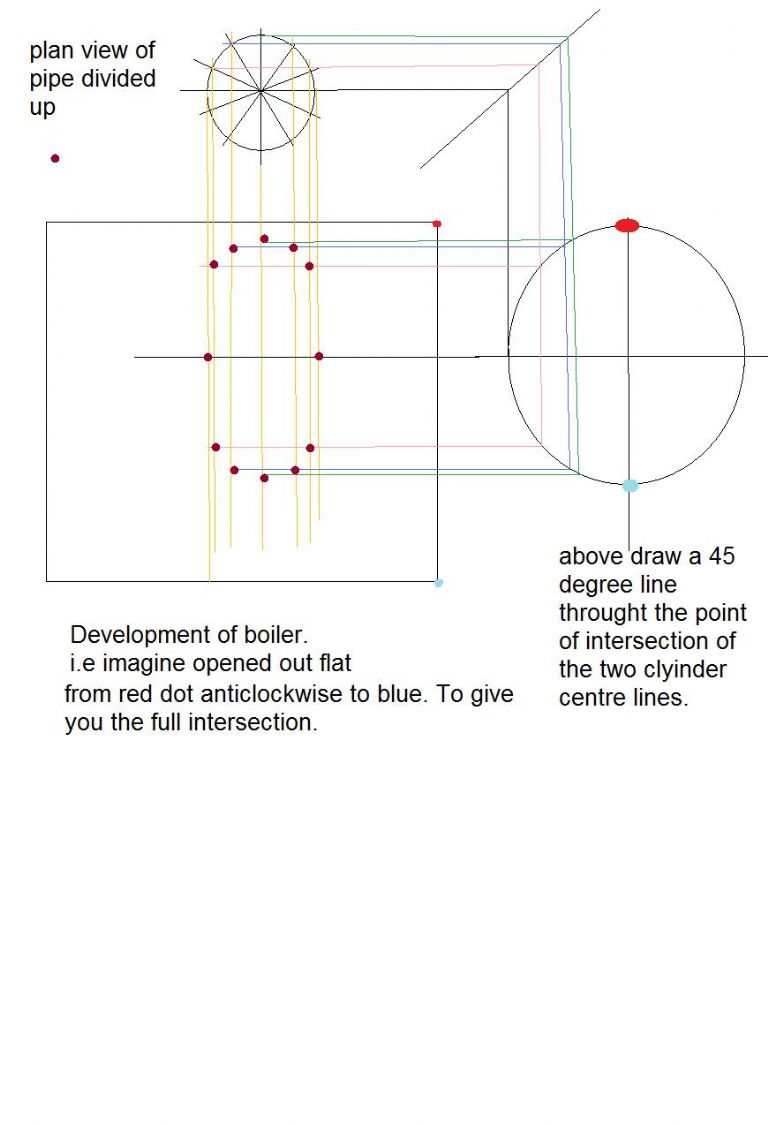 |
| Vincent Shaw-Morton | 09/12/2010 09:44:51 |
| 17 forum posts 15 photos | Thanks for your help everyone, there are some great solutions here that I can use
Best
Vincent
|
| Clive Farrar | 09/12/2010 21:19:32 |
125 forum posts 41 photos | Hi Vincent,
its been bugging me all day that my diagram may NOT correct. As its 30 odd years since i last did this sort of thing I have missed a bit out.
So I think if you use this method you need to test it out on something unimportant like a toilet role core.
So what have i done wrong? the red dot blue dot on the circle is the boiler diameter but when you develop that out into the flat it becomes half the circumference i.e 3.142 times longer.
Some how there needs to be an intersect line intersposed between the boiler circle and boiler development such that as you transfer the lines across they correct the positioning by a factor of Pi but at the moment I can not remember how.
Not sure if I have made that better or worse but it gives you a starting point for a net search.
If you give me diameters and aproximate location I will try and get some time to do it properly but with work at the moment i can not promise.
Regards Clive |
| JasonB | 10/12/2010 07:38:43 |
25215 forum posts 3105 photos 1 articles | Have a look at this google book, about 6 pages in it gives you what you need
J |
| John Olsen | 10/12/2010 09:27:47 |
| 1294 forum posts 108 photos 1 articles | Clive, what your projection produces is the view of what the tube would look like while it is round. If you want to develop the shape of the tube as it would be if flattened out you have to do more work. You could draw radial division in the circle on the right, then project them across your developed shape. The radial lines would be getting closer together there as you get further from the centre. You then draw a similar grid of lines, but with the horizontal lines at a constant spacing, equal to the circumferential distance between each radial line. Transfer the sizes from the original set to the new set, and it will stretch the shape at the ends by the right amount. However, unless the plan is to cut the hole and then roll the tube shape, which I would not advise, that approach should not be needed. The problem is not to find what shape the hole would be if the tube were flattened, it is to make a hole which is reasonably close to round in the actual tube The other thing is your smaller tube seems to be meeting the larger tube at a tangent. The original problem was for a dome bush, which would mean that the centre lines of the two tubes (extended) would meet. I did a tube like yours once for a model water tube boiler, of a simple Babcock and Wilcox type. Simple because it only had one bank of tubes, which used a cross tube across the drum for a header. I made the semi elliptical cutout by just filing until I had a good fit... regards John |
| Clive Farrar | 10/12/2010 15:08:02 |
125 forum posts 41 photos | John and All as stated I realised my original drawing was not the full story.
And yes it does look like a tangent application but it was the only way i could get the template profile that would need to laid over , curved round the boiler to scibe a line that when cut would be the circular hole required.
Rather than fiddle about and misslead some more i had a quick look on the web and came up witht he following link.
about half way through it does the intersection of two cyinders. That is what i was trying to convey but failed to do so correctly. I was close though
 Regards Clive |
Please login to post a reply.
Magazine Locator
Want the latest issue of Model Engineer or Model Engineers' Workshop? Use our magazine locator links to find your nearest stockist!
Sign up to our Newsletter
Sign up to our newsletter and get a free digital issue.
You can unsubscribe at anytime. View our privacy policy at www.mortons.co.uk/privacy
Latest Forum Posts
- *Oct 2023: FORUM MIGRATION TIMELINE*
05/10/2023 07:57:11 - Making ER11 collet chuck
05/10/2023 07:56:24 - What did you do today? 2023
05/10/2023 07:25:01 - Orrery
05/10/2023 06:00:41 - Wera hand-tools
05/10/2023 05:47:07 - New member
05/10/2023 04:40:11 - Problems with external pot on at1 vfd
05/10/2023 00:06:32 - Drain plug
04/10/2023 23:36:17 - digi phase converter for 10 machines.....
04/10/2023 23:13:48 - Winter Storage Of Locomotives
04/10/2023 21:02:11 - More Latest Posts...
- View All Topics
Support Our Partners


Shopping Partners
Subscription Offer

Latest "For Sale" Ads
- Reeves** - Rebuilt Royal Scot by Martin Evans
by John Broughton
£300.00 - BRITANNIA 5" GAUGE James Perrier
by Jon Seabright 1
£2,500.00 - Drill Grinder - for restoration
by Nigel Graham 2
£0.00 - WARCO WM18 MILLING MACHINE
by Alex Chudley
£1,200.00 - MYFORD SUPER 7 LATHE
by Alex Chudley
£2,000.00 - More "For Sale" Ads...
Latest "Wanted" Ads
- D1-3 backplate
by Michael Horley
Price Not Specified - fixed steady for a Colchester bantam mark1 800
by George Jervis
Price Not Specified - lbsc pansy
by JACK SIDEBOTHAM
Price Not Specified - Pratt Burnerd multifit chuck key.
by Tim Riome
Price Not Specified - BANDSAW BLADE WELDER
by HUGH
Price Not Specified - More "Wanted" Ads...
Get In Touch!
Do you want to contact the Model Engineer and Model Engineers' Workshop team?
You can contact us by phone, mail or email about the magazines including becoming a contributor, submitting reader's letters or making queries about articles. You can also get in touch about this website, advertising or other general issues.
Click THIS LINK for full contact details.
For subscription issues please see THIS LINK.
Digital Back Issues


Donate

 Register
 Log-in
Model Engineer Magazine
- Percival Marshall
- M.E. History
- LittleLEC
- M.E. Clock

ME Workshop
- An Adcock
- & Shipley
- Horizontal
- Mill

Subscribe Now
- Great savings
- Delivered to your door

Pre-order your copy!
- Delivered to your doorstep!
- Free UK delivery!
All Forum Topics > Beginners questions > Pprojecting a circle onto a boiler barrel