Forum sponsored by:

Fradley Canal Crane Progress
| Stub Mandrel | 23/05/2010 21:03:42 |
 4318 forum posts 291 photos 1 articles | The crane is nearly finished - just needs a suitable chain and hook. 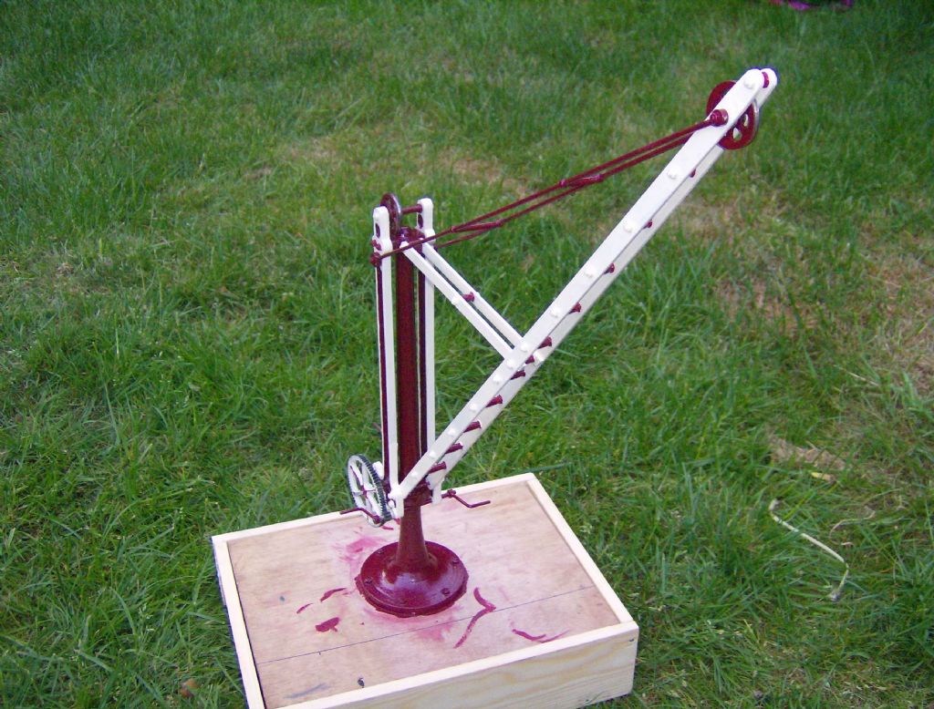 You can see (just) how I dealt with the missing pulley problem - its at the top, but offset. This nasty box is going to become a short section of canal towpath, with a cement base for the crane and DAS clay stones along one edge. 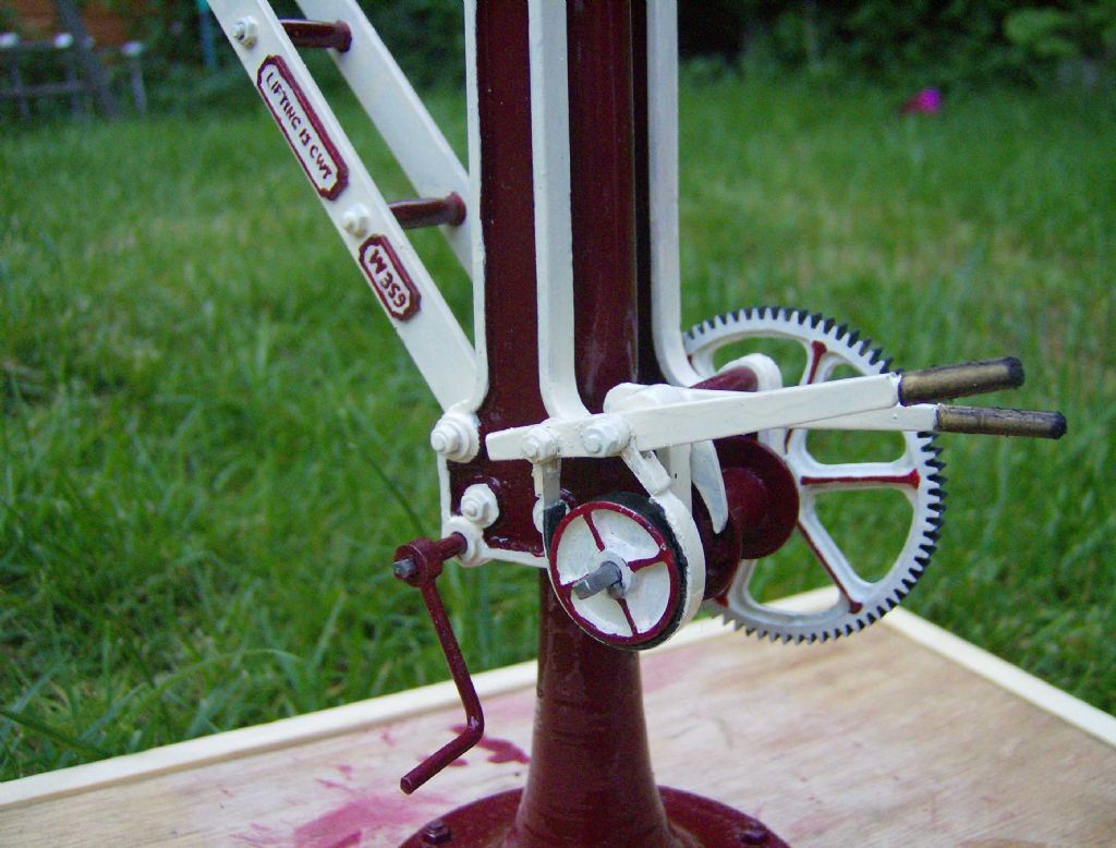 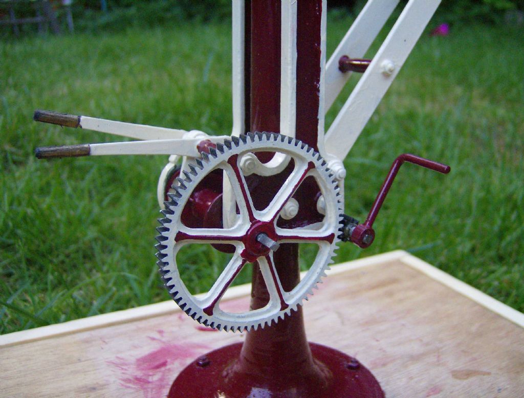 The flash and the close up aren't too kind to my paint job!! Neil |
| Frank Dolman | 24/05/2010 00:44:54 |
| 106 forum posts | It's nice. We know that it is an accurate model because you allowed us to keep track of your enquiries. I only hope that other viewers give you
the credit that it deserves! |
| Stub Mandrel | 29/05/2010 20:42:46 |
4318 forum posts 291 photos 1 articles | Crane now finished! It works too, using winder, ratchet and brake, as long as the hook is holding a couple of ounces. The chain is brass, but I got Jenoloite Koldblak to work on it. 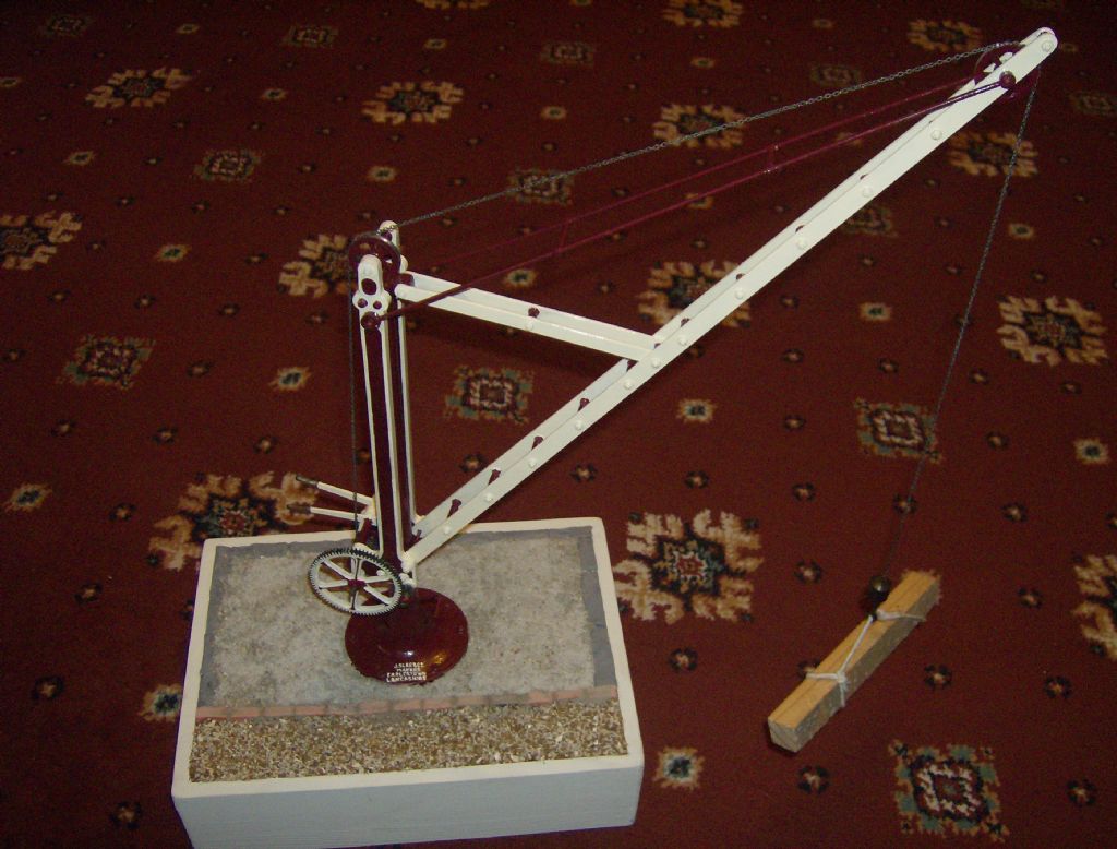 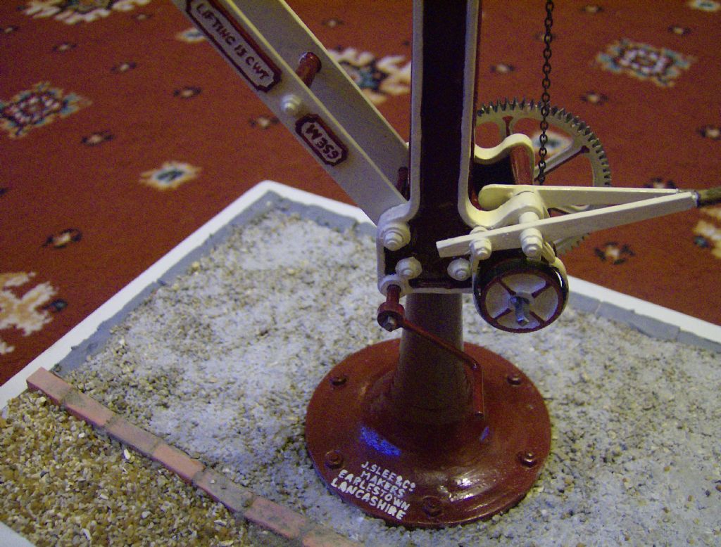 Thanks to all who gave advice and ideas. My daughter says its cool, so that's something  Neil |
| Ramon Wilson | 29/05/2010 21:40:55 |
 1655 forum posts 617 photos | As alluded to elsewhere Neil, you should be well pleased with your labours. Congratulations then on finishing this rather unusual, well researched and accurately made model. You've made a lovely job of it and your attention to detail and the final presentation has produced a very realistic rendition.
I look forward to following your next unusual prototype
 Kind regards - Ramon |
| Alan Bays | 20/01/2020 22:00:34 |
| 11 forum posts | Question for Neil or anyone here who has built this from his plans: the jib is shown as a bit over 8" long on the plan, which is clearly incorrect based on the column height. Are the published dimensions for this 50% actual? In which case is the jib thickness still 1/16" x 1/4" or should it be 1/8" x 1/2"? |
| Steviegtr | 20/01/2020 22:04:40 |
 2668 forum posts 352 photos | Brilliant. Love it. Well done. |
| Chris Evans 6 | 21/01/2020 15:32:44 |
 2156 forum posts | A timely thread resurrection, I have just walked the dog to Fradley Junction from home in Kings Bromley. I will look out for the original crane on my next walk. |
| Neil Wyatt | 21/01/2020 16:22:14 |
 19226 forum posts 749 photos 86 articles | Posted by Alan Bays on 20/01/2020 22:00:34:
Question for Neil or anyone here who has built this from his plans: the jib is shown as a bit over 8" long on the plan, which is clearly incorrect based on the column height. Are the published dimensions for this 50% actual? In which case is the jib thickness still 1/16" x 1/4" or should it be 1/8" x 1/2"? I think rogue auto dimensioning may have meant that one version of the plans had wrong dimensions when the jib was scaled to fit the page. The plans have been revised, these are the correct dimensions:
|
| Michael Gilligan | 21/01/2020 17:18:31 |
 23121 forum posts 1360 photos | Posted by Neil Wyatt on 21/01/2020 16:22:14:
[…] I think rogue auto dimensioning may have meant that one version of the plans had wrong dimensions when the jib was scaled to fit the page. […]
. Looks like you might need to start counting the Angels and Demons, Neil
|
| Martin W | 21/01/2020 17:36:42 |
| 940 forum posts 30 photos | For them that's interested pictures can be seen here, if moderators think this infringes on IP then please delete. Martin |
| Neil Wyatt | 21/01/2020 19:11:03 |
19226 forum posts 749 photos 86 articles | Also photos of the crane and work in progress here: www.model-engineer.co.uk/albums/member_album.asp?a=9872 Neil |
| Alan Bays | 22/01/2020 17:50:21 |
| 11 forum posts | Thanks Neil, that's what I had assumed. A couple of follow up questions: What's the width of the jib material? It's not dimensioned on the plan, but looks to be about 3/8" . Also, the width of the top spacer is shown as 1" while the bottom spacer is 1 1/8" . That difference would make the main frames taper slightly towards the top. Is that correct? From the photos they look to be parallel. |
| JasonB | 22/01/2020 18:18:13 |
 25215 forum posts 3105 photos 1 articles | Neil, your revised drawing has two dimension lines that don't point to anything, the 3 1/16" and the 8 13/32" Edited By JasonB on 22/01/2020 18:26:39 |
| Former Member | 22/01/2020 18:22:27 |
| 1329 forum posts | [This posting has been removed] |
| Former Member | 22/01/2020 18:34:01 |
| 1329 forum posts | [This posting has been removed] |
| JasonB | 22/01/2020 18:39:52 |
25215 forum posts 3105 photos 1 articles | Bill, that is one end of the 8 13/32" which does not relate to anything. Also just noticed there are two lines at bottom right with the lower one not related to anything but is one end of the 16 1/2" dimension. Should have used Alibre |
| Neil Wyatt | 22/01/2020 18:58:08 |
19226 forum posts 749 photos 86 articles | The two orphan dimensions should go to the holes they miss by a bit, both of which are correctly positioned if half-way between the holes on either side of them. 5/16" wide. Here's a revision, as good as I can get with Corel Draw, which keeps snapping to odd places so some of the lines are poorly aligned. Not sure overall length is spot on, do it by eye to match the hole, note the taper at the far end which is very important for a good appearance This is why I use proper drawing programs these days...
Edited By Neil Wyatt on 22/01/2020 19:03:09 Edited By Neil Wyatt on 22/01/2020 19:04:53 |
| JasonB | 22/01/2020 19:03:26 |
25215 forum posts 3105 photos 1 articles | Posted by Neil Wyatt on 22/01/2020 18:58:08:
3/16" wide. But you have added a 5/16" width dimension. However 3/8" width would seem to work better as that would give a 3/16" radius at the bottom and say 1/8" radius at the top and therefore 3/16 + 1/8 + 16 1/2" + 3/4" = the 17 9/16" overall length from the first revision you posted
Edited By JasonB on 22/01/2020 19:09:46 |
| Neil Wyatt | 22/01/2020 19:10:58 |
19226 forum posts 749 photos 86 articles | Posted by JasonB on 22/01/2020 19:03:26:
Posted by Neil Wyatt on 22/01/2020 18:58:08:
3/16" wide. But you have added a 5/16" width dimension. However 3/8" width would seem to work better as that would give a 3/16" radius at the bottom and say 1/8" radius at the top and therefore 3/16 + 1/8 + 16 1/2" + 3/4" = the 17 9/16" overall length. Edited By JasonB on 22/01/2020 19:04:05 Pretty sure it's 5/16, problem is the dimensions are a law unto themselves... some seem to have aligned with centres of holes others with circumferences and then the auto functions rounds them... The problem is the program doesn't seem to let you edit starting points if snapped to objects and you ahve to zoom out to see the whole extent when you place them which means you can't be picky about where they start/finish. As I say, this is why I use proper software now... The main holes are 18" apart on the real thing, 1 1/2" on the model. A quick look at the photos of model or real thing should be enough to get it looking right. |


Please login to post a reply.
Magazine Locator
Want the latest issue of Model Engineer or Model Engineers' Workshop? Use our magazine locator links to find your nearest stockist!
Sign up to our Newsletter
Sign up to our newsletter and get a free digital issue.
You can unsubscribe at anytime. View our privacy policy at www.mortons.co.uk/privacy
Latest Forum Posts
- *Oct 2023: FORUM MIGRATION TIMELINE*
05/10/2023 07:57:11 - Making ER11 collet chuck
05/10/2023 07:56:24 - What did you do today? 2023
05/10/2023 07:25:01 - Orrery
05/10/2023 06:00:41 - Wera hand-tools
05/10/2023 05:47:07 - New member
05/10/2023 04:40:11 - Problems with external pot on at1 vfd
05/10/2023 00:06:32 - Drain plug
04/10/2023 23:36:17 - digi phase converter for 10 machines.....
04/10/2023 23:13:48 - Winter Storage Of Locomotives
04/10/2023 21:02:11 - More Latest Posts...
- View All Topics
Support Our Partners


Shopping Partners
Subscription Offer

Latest "For Sale" Ads
- Reeves** - Rebuilt Royal Scot by Martin Evans
by John Broughton
£300.00 - BRITANNIA 5" GAUGE James Perrier
by Jon Seabright 1
£2,500.00 - Drill Grinder - for restoration
by Nigel Graham 2
£0.00 - WARCO WM18 MILLING MACHINE
by Alex Chudley
£1,200.00 - MYFORD SUPER 7 LATHE
by Alex Chudley
£2,000.00 - More "For Sale" Ads...
Latest "Wanted" Ads
- D1-3 backplate
by Michael Horley
Price Not Specified - fixed steady for a Colchester bantam mark1 800
by George Jervis
Price Not Specified - lbsc pansy
by JACK SIDEBOTHAM
Price Not Specified - Pratt Burnerd multifit chuck key.
by Tim Riome
Price Not Specified - BANDSAW BLADE WELDER
by HUGH
Price Not Specified - More "Wanted" Ads...
Get In Touch!
Do you want to contact the Model Engineer and Model Engineers' Workshop team?
You can contact us by phone, mail or email about the magazines including becoming a contributor, submitting reader's letters or making queries about articles. You can also get in touch about this website, advertising or other general issues.
Click THIS LINK for full contact details.
For subscription issues please see THIS LINK.
Digital Back Issues


Donate

 Register
 Log-in
Model Engineer Magazine
- Percival Marshall
- M.E. History
- LittleLEC
- M.E. Clock

ME Workshop
- An Adcock
- & Shipley
- Horizontal
- Mill

Subscribe Now
- Great savings
- Delivered to your door

Pre-order your copy!
- Delivered to your doorstep!
- Free UK delivery!
All Forum Topics > Miscellaneous models > Fradley Canal Crane Progress