Forum sponsored by:

Phase Converter Which Type?
Trying to work out what type of phase converter to get
| Aidan Browne | 02/08/2009 23:17:17 |
| 15 forum posts | Hi, I recently got the chance to buy an Ajax AJT4 Turret Mill with a 3Hp motor on it. I only have a standard single phase supply and I am wondering what sort of converter to buy. The more I read the more conflicting information I get. A Static Converter has to be matched up and it seems that there is no overload protection and you are not really getting true 3 phase. More like 2 phase and a phantom 3 phase. Rotory Converter seems to be a good job but has to spin up to speed and remain running. Not Really ideal for start stop milling work. The one I like is the Digital Phase converter but there seems to be some controversy about the supply drawn from the mains. I would really like to hear from anybody that has experience in this area as the more I read the more confused about the truth I get. Thanks. |
| John Stevenson | 02/08/2009 23:54:53 |
 5068 forum posts 3 photos | Aidan. You are correct with your understanding of a static converter, they are a fudge. The rotary once running can be left running and you start and stop the mill motor on it's normal controls. the rotary converter doesn't replace the machine controls more live it supplies your 3 phase electrical supply. Can be noisy but they are needed for things like 2 speed motors which require a true 3 phase supply. Digital Phase converter or Inverter or VFD depending on who's terminology you use take in single phase and spit out 3 phase but at 240 volts and for this you need a motor that can be rewired from star to delta. Basically the terminal box on the side of the motor needs 6 terminals. 3Hp or 2.2 Kw is about the maximum you can get on single phase and a quick look in a manual rates one of these at 11 amps input current. One advantage of these inverters is that it's possible to get variable speed and so save changing belts as much. They also have the added advantage of soft start and breaking and are a lot better for the motor, they also monitor the motor and provide overload features far better than the old thermal trips as fitted to the push button startes of old. John S. |
| David Thomas 6 | 04/08/2009 09:50:13 |
| 4 forum posts 1 photos | I have experience of Inverters/VFDs in a home workshop, but not the static and rotary converters. The VFD (my two are Parker SSD models) is great: quiet, flexible, small and neat, and I think very safe. It provides soft start, no-volt stop and flexible speed control. However: - with a 240V supply, you will only get 240V 3-phase and (as John says) will need a VFD sized to output 11 amps. (The good news is that the soft start controls inrush current, and you don't need to cater for a momentary 60 or 80 amps at start) - you will need to buy or make a control box which replaces the existing push buttons on the mill, and is permanently wired into the inverter. I made mine from components I got from RS, and the total cost was £50-60 for On, Stop, Jog and Reverse pushes and switches, contact blocks, potentiometer, enclosure etc : in addition to the cost of the inverter itself - the inverter must have an EMC filter (radio intereference) fitted and must be wired carefully using screened cables, because it works by creating phase differences and a side-effect is electrical 'noise' - for the same reason, you will need to plug it into a circuit which is protected by circuit breaker (MCB) but not a residual current device (RCD), because the inverter creates earth leakage (or it may just be a sort of phantom earth leakage because that's what the phase difference 'looks like' to the equipment, I'm not sure). Whatever it is, it will trip an ordinary domestic RCD. I am not an electrician, but I suspect the latest wiring regulations require any NEW sockets to be RCD protected, so whether this creates a problem depends on your wiring and circumstances. - the latest MEW contains an article about converting a 3HP Harrison lathe to inverter drive, and suggests that there is a correct way to install the power supply under the latest regulations: I think the author understands the details better than I do. |
| David Thomas 6 | 04/08/2009 10:48:46 |
| 4 forum posts 1 photos | .... oh, and here's a sketch of the control wiring required. Use at your own discretion and risk. 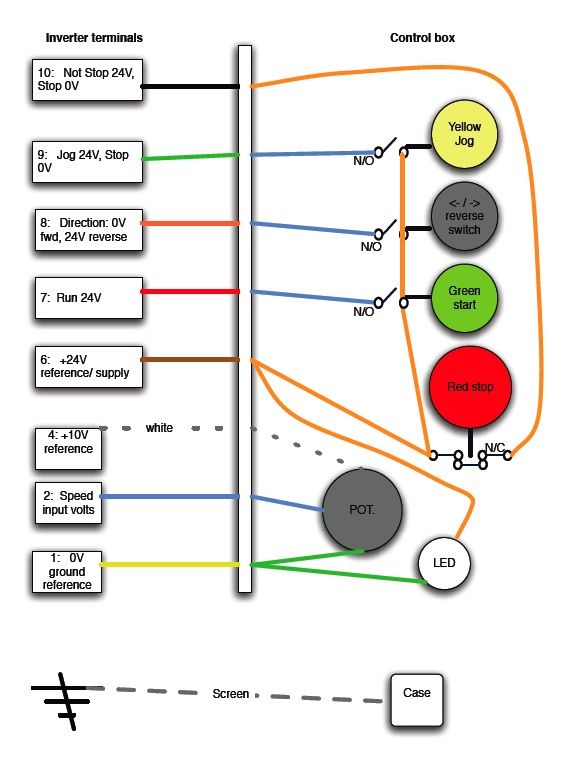 Edited By David Thomas 6 on 04/08/2009 10:50:34 |
| Aidan Browne | 04/08/2009 22:26:42 |
| 15 forum posts | Thanks for taking the time to write such detailed responses. I'm convinced now to go for the Inverter type. I was looking on Ebay and came across Direct Drives and this inverter http://cgi.ebay.ie/3HP-3-PHASE-INVERTER-CONVERTER-LATHE-MILLING-DRILL-SAW_W0QQitemZ270404656397QQcmdZViewItemQQptZUK_BOI_ Industrial_Automation_Control_ET?hash=item3ef55f9d0d&_trksid=p3286.c0.m14 I rang and was speaking to dave who told me about having to get the added control pod as he put it which is exactly what david above has kindly put up the plans for. Also the motor has to be change from a Star to Delta mode. If anyone has any experience of these Direct Drive Inverters I would like to hear from you. The feedback on Ebay seems to be positive. I have a power feed on the table which as far as I know is 110V so I will have to buy a 230-110 Transformer for that as well. But at least I'll be set up properly. Edited By Aidan Browne on 04/08/2009 22:27:44 |
| Dugson | 05/08/2009 00:44:59 |
| 11 forum posts | You may find that there is a transformer in the machine which supplies the 110v from a 415v input, Sometimes these transformers have other voltage taps, it might be worth a look |
| Aidan Browne | 17/08/2009 22:36:44 |
| 15 forum posts | Hi All, Just to give you an update I bought an Inverter from Direct Drives in Nottingham. They were £212 to buy direct but he was also selling them on ebay where I bought mine for £137 which is a 3HP Inverter. It was really east to set up I just chanded the motor to a delta configuration (5 minutes) and wired the inverter direct to the motor. I bought the remote control pad as well which cost me £20 but I have forward / stop /reverse on one switch and a variable dial to control the speed of the motor also.(Also still use the mechanical speed control on the mill, which I think I will use) It took only a couple of minutes to wire and setup and so far so good. I have not done any heavy milling yet to see if it will drop in power, but I'm assured from direct drives that it will work fine. I'll keep you posted if there are any problems. Thanks for the advice  By the way: The inverter will not drive any transformers just motors so I got a cheap industrial 110V building site tranformer and wired my power feed to it so I'm setup now. You can buy inverters that will do such a thing (plug and play I think they are called), but they are big money. |
| Gray62 | 23/08/2010 23:52:19 |
| 1058 forum posts 16 photos | HI Aidan, I also have an AJt4, I fitted it with 2 inverters from Direct drives, one to run the spindle and the other to run the feed motor. I utilised the existing control ppod and aded some relays to do the switching. If anyone is interested I will produce a wiring diagram of how to achieve this. The suds pump is currently unused as I use an air powered fog free coolant spray system of my own design however, as the suds pump motor is only 1/8 hp, it can easily be run on a single phase supply with a phase capacitor supplying the 'dummy' 3rd phase, again, if anyone needs detailse let me know and I will provide the necessary info regards coalburner |
| John Olsen | 24/08/2010 01:28:28 |
| 1294 forum posts 108 photos 1 articles | Hi All, Well, I agree that the inverter is the way to go these days, especially for machines where the variable speed is an asset. But I would like to point out something that appears not to be generally known. You can in fact buy inverters which take the normal 230 Volt supply in and spit out 415 Volts for the motor. Naturally they are more expensive, but could be the way to go for machines that cannot be rewired for the lower Voltage. They are still limited to the power that you can take from the single phase, naturally enough. So if you find your machine has a 415 Volt motor which is already Delta connected for that Voltage, there is a way around it. There is a regular advertiser in the Model Engineer selling this type of inverter, I have not had anything to do with them so cannot comment, but that could be a place to start if you need this sort of solution. There was a brief comment earlier on the way the digital inverters work. What they actually do is rectify the incoming mains to DC, which would be at about 325 Volts (230 times root 2) Then they have three inverters, one for each phase, and each inverter chops the DC back up into a reasonable approximation of an AC wave. When I say "reasonable" at the higher speeds the wave may actually be just a square wave. Naturally switching a highish voltage creates a bit of electrical noise, and you may also get the odd funny noise from the motor winding at certain speeds where it happens to be getting a wave form that is a bit strange. This doesn't seem to matter in the slightest. I haven't seen the innards, but I suspect that the 230 to 415 inverters mentioned are using a Voltage doubling rectifier. There isn't room inside them for a transformer anyway! Well, unless they are using a switch mode power supply type of arrangement. These drives are highly programmable, and for instance you can set the maximum speed to be much higher than normal. I have one here where I am running a 1/4 hp three phase motor up to 100 Hz instead of 50. For reasons we don't want to go into in depth here, you can't get the full torque at those higher speeds, but it is a handy thing to be able to do if you need to. Most good quality motors are OK to much higher speeds than they normally run at. (But watch out for the maximum speeds of spindles, chucks etc!) regards john |
| John Coates | 24/08/2010 12:24:17 |
 558 forum posts 28 photos | A really useful thread btw folks as I plan to change my lathe and mill to 3 phase for the variable speed at some time in the future so this is great for my research
One thing that hasn't been touched on yet is replacing 1 phase motors to be able to take advantage of this. I know old motors (1940's on my lathe) have a footprint - something along the lines of B56 for mine I seem to recall - and then there is the spindle (5/8" on my lathe) whereas a lot of the 3 phase motors seem to have bigger spindles
But if I can summarise what has been said I will need an inverter with a speed controller, a switch or isolator to switch between lathe and mill, a new motor for each machine. I like the idea of re-wiring the controls on the mill though. Mine is a Chester Champion with start/stop/reverse/isolate whereas the lathe just has a Dewhurst forward/stop/reverse lever switch
Keep on posting and I'll keep reading
John |
| KWIL | 24/08/2010 15:39:57 |
| 3681 forum posts 70 photos | As has been mentioned in another place, do you not find it strange that there is ONLY ONE advertiser offering 415V 3ph out? They are clearly from the same source as the others in the advert but has an "own" label, I wonder if this is a local fix? CE marked? All of my own machines are Inverter driven with integrated safety controls, they were of course all previously 3 phase machines or have been upgraded from single phase (the Myfords only) Edited By KWIL on 24/08/2010 15:41:04 |
| John Stevenson | 24/08/2010 20:46:03 |
5068 forum posts 3 photos | They are an "own fix" and as such because many of the components were never intended for 440 v operation they can never be CE approved. This is not my take on it but from a drives technician who has works for many of the large manufacturers. When you get one of these guys on-site to sort a problem out and they can clearly explain what EVERY one of the 400 odd parameters does and how to set up for the optimum result they are worth every penny. John S. |
| John Coates | 25/08/2010 20:33:40 |
558 forum posts 28 photos | If my single phase motor on my 1947 lathe is rated at 1425 rpm and I'm thinking of going 3 phase, is there a limit to the capacity of the 3 phase inverter I could buy? e.g. there are various converters offered by Transwave and Digital from 1/8th HP up to 10 HP. I don't know what my lathe motor equates to but I would guess 3/4 HP to 1 HP working on Myford equivalents Could I get a 1 HP or 3 HP inverter in their eBay sales and match that to a 1 HP or 3 HP star/delta motor Would this cause any problems for my lathe? |
| John Olsen | 25/08/2010 23:03:09 |
| 1294 forum posts 108 photos 1 articles | Well, you could be right that there is a problem with them, although I think they would be pretty brave going to market with a product if there is any doubt. I have been told that such an inverter is available locally in NZ, so I will follow that up and see what I can find out. Perhaps somone at the UK end of things would like to check up on what sort of guarantee is offered with the particular devices. I can tell you a few things: 1/ In principle it is possible to do this safely. It will be more complex than a standard inverter. it will either need a voltage doubling rectifier on the mains, which calls for some expensive capacitors, or else a switch mode power supply to change the rail voltage internally from about 325V to about 650V. Rated of course for the full power of the drive. So it would be more expensive to do. 2/ It may occur to someone to use a transformer to step up to 230 Volts to 415 V and apply this to a three phase to three phase inverter. THIS WOULD NOT BE A GOOD IDEA! Apart from the size and cost of the necessary transformer, the rectifier in the motor control is not designed to be used in that way. A three phase rectifier fed with three phase power has a ripple frequency three times that of the equivalent rectifier on single phase, so there is much less ripple. Also the peak currents through the diodes are less. So using a device meant for three phase input on a single phase would not be wise. (If the device is well designed, it might detect the absence of the extra phases and shut down.) Converting the rectifier would call for bigger filter capacitors and bigger diodes, since the peak current through the diodes will be about three times as high 3/ I would not expect an inverter for this purpose to be very commonly made, since the main market would be people like ourselves trying to upgrade older machines, or machines where the motor is not easily changed, and where three phase power is not readily available. In industry, three phase power is more commonly available than not. So it is not too surprising if there are not too many sources for them. John Coates....Your inverter needs to have a capacity large enough for the horsepower of the motor you use with it. It does not need to be oversized. Since a three phase motor has better starting torque than a single phase motor, you don't need to put on anything more powerful than you already have. If you don't know what it is, someone with experience around motors will be able to tell you from the frame size. The 1425 RPM speed means that it is a two pole motor. If you put on a two pole three phase motor, you will get essentially the same range of speeds with a controller, although the controller can run the motor faster if you wish. (They often come set as a default to allow you to run the motor up to 60Hz.) If you decide to set the controller up to allow running the lathe faster than before, bear in mind that the spindle bearing may not be meant for this, so don't overdo things. The three phase motor of the same power will be smaller and lighter and will vibrate less, so if anything will remove problems from your lathe. |
| John Stevenson | 26/08/2010 00:24:18 |
5068 forum posts 3 photos | Posted by John Olsen on 25/08/2010 23:03:09: The 1425 RPM speed means that it is a two pole motor. If you put on a two pole three phase motor, you will get essentially the same range of speeds with a controller, although the controller can run the motor faster if you wish. . . A 1425 motor is a 4 pole motor, 2 pole motors run at 2850 revs here in the Uk on 50 cycles. John S. |
| Andrew Johnston | 26/08/2010 10:09:52 |
 7061 forum posts 719 photos | As I understand it the traditional way to get 415V three phase from 240V single phase via an inverter is to put a three phase step-up transformer on the output of the inverter. Like some of the other respondents I did a quick internet search and didn't find anybody else selling 240V single phase in, 415V three phase out inverters. Seems slightly odd, apart from the obvious point, already made, about a limited market. One would assume that any half decent inverter should be using active PFC (power factor correction) in the initial AC to DC stage. Assuming that one wanted to build the said inverter I would have thought that the simplest way would be to adapt the active PFC to a incorporate a boost converter. This would be fairly efficient and since it should be switching in the 100kHz region and the inductors will be fairly small. After that just use the standard three phase half bridge, rated for the appropriate voltage. Regards, Andrew |
| John Olsen | 26/08/2010 10:59:01 |
| 1294 forum posts 108 photos 1 articles | Yes, you are quite right...I realised after I was away from the computer that I had got the number of poles totally wrong. So two poles would do about 2800RPM, 4 poles 1400 or so. I did talk to a friend who is more current with motor controls and power electronics than I, he said that 230 in 415 out inverters are made although not common. He was of the opinion that such a device is not likely to be a lash up, power electronic stuff tends to either work forever or destroy itself very quickly. That was certainly my experience when I did a design project on a small high speed inverter for a University project 30 years ago, with one of the pioneers in the field. That one ran off 600 Volts, and the devices were rated for 12 Amps. There is no fuse made that is fast enough to save such devices if the inverter fails to commutate. Of course there are better switching devices made now. Is the boost convertor and active PFC not effectively a form of switch mode power supply anyway? A three phase rectifier intended for 415 Volt three phase at 50Hz might not be too happy being fed with 100 kHz regards John |
| Andrew Johnston | 31/08/2010 21:09:02 |
7061 forum posts 719 photos | Indeed an active PFC boost converter is a type of switch-mode power supply. The problem with a passive voltage doubler is that it doesn't provide quite enough headroom on the DC bus to generate a three phase supply from a single phase supply, if you want to maintain the same phase to neutral voltages from input to output. Hence the need for an active boost converter. I'm not sure where 100kHz gets fed to a three phase rectifier. The PFC converter runs at, say 100kHz, creating a DC bus which then feeds the three phase half bridges that generates the AC output. The newer styles of PFC converter do away with the input rectifiers, thus saving the energy lost in the diode drops. The informal group I work with designed what is essentially an AC to DC boost converter last year. It turned out to be quite a design challenge mechanically, as the unit is only 300x300x120mm and is rated at 30kW in an ambient temperature of 100°C. Liquid cooled of course. The unit takes the three phase output from a generator on a diesel engine and outputs 600VDC. Of course once the hardware is in place it is trivial (software changes) to run the converter in reverse and use the 600VDC to generate a three phase supply which uses the generator as a motor and starts the engine. Regards, Andrew |
| John Olsen | 31/08/2010 23:44:36 |
| 1294 forum posts 108 photos 1 articles | Ok, I wasn't sure if the boost converter was going to incorporate its own rectifier or not. It would of course need to, because the diodes meant for the three phase are probably not going to be fast enough to cope. regards John |
| Richard Parsons | 01/09/2010 10:08:10 |
 645 forum posts 33 photos |
I wish someone would have a look at Single phase speed controllers for a ‘Squirrel Cage’ motors. Something with a limited frequency range say from 50Hz (CPS in old money) down to 20 Hz.. I do not want to run my machines at huge speeds nor do I want all of the bells, whistles, gongs and hooters nor can I afford the cost of replacing my perfectly good single phase motors with expensive 3 phase units.
My lathes have some blind spots in their speed ranges which are either very difficult to engage or make nasty grongeling noises. |
Please login to post a reply.
Magazine Locator
Want the latest issue of Model Engineer or Model Engineers' Workshop? Use our magazine locator links to find your nearest stockist!
Sign up to our Newsletter
Sign up to our newsletter and get a free digital issue.
You can unsubscribe at anytime. View our privacy policy at www.mortons.co.uk/privacy
Latest Forum Posts
- *Oct 2023: FORUM MIGRATION TIMELINE*
05/10/2023 07:57:11 - Making ER11 collet chuck
05/10/2023 07:56:24 - What did you do today? 2023
05/10/2023 07:25:01 - Orrery
05/10/2023 06:00:41 - Wera hand-tools
05/10/2023 05:47:07 - New member
05/10/2023 04:40:11 - Problems with external pot on at1 vfd
05/10/2023 00:06:32 - Drain plug
04/10/2023 23:36:17 - digi phase converter for 10 machines.....
04/10/2023 23:13:48 - Winter Storage Of Locomotives
04/10/2023 21:02:11 - More Latest Posts...
- View All Topics
Support Our Partners


Shopping Partners
Subscription Offer

Latest "For Sale" Ads
- Reeves** - Rebuilt Royal Scot by Martin Evans
by John Broughton
£300.00 - BRITANNIA 5" GAUGE James Perrier
by Jon Seabright 1
£2,500.00 - Drill Grinder - for restoration
by Nigel Graham 2
£0.00 - WARCO WM18 MILLING MACHINE
by Alex Chudley
£1,200.00 - MYFORD SUPER 7 LATHE
by Alex Chudley
£2,000.00 - More "For Sale" Ads...
Latest "Wanted" Ads
- D1-3 backplate
by Michael Horley
Price Not Specified - fixed steady for a Colchester bantam mark1 800
by George Jervis
Price Not Specified - lbsc pansy
by JACK SIDEBOTHAM
Price Not Specified - Pratt Burnerd multifit chuck key.
by Tim Riome
Price Not Specified - BANDSAW BLADE WELDER
by HUGH
Price Not Specified - More "Wanted" Ads...
Get In Touch!
Do you want to contact the Model Engineer and Model Engineers' Workshop team?
You can contact us by phone, mail or email about the magazines including becoming a contributor, submitting reader's letters or making queries about articles. You can also get in touch about this website, advertising or other general issues.
Click THIS LINK for full contact details.
For subscription issues please see THIS LINK.
Digital Back Issues


Donate

 Register
 Log-in
Model Engineer Magazine
- Percival Marshall
- M.E. History
- LittleLEC
- M.E. Clock

ME Workshop
- An Adcock
- & Shipley
- Horizontal
- Mill

Subscribe Now
- Great savings
- Delivered to your door

Pre-order your copy!
- Delivered to your doorstep!
- Free UK delivery!
All Forum Topics > Model Engineers' Workshop. > Phase Converter Which Type?