Forum sponsored by:

Rotary Table setup
| Vic | 22/12/2022 23:05:32 |
| 3453 forum posts 23 photos | Can any of you recommend a good online source of information on buying, setting up and using a Rotary Table. I don’t yet have one but I have a few projects in mind that will require one. TIA. |
| Mark Davison 1 | 22/12/2022 23:24:09 |
| 134 forum posts 38 photos | Try Joe Pie on YouTube |
| Michael Gilligan | 22/12/2022 23:32:18 |
 23121 forum posts 1360 photos | There’s some good information here, Vic : **LINK** https://www.micro-machine-shop.com/rf_mill_accessories.htm#Rotary_Tables MichaelG. . Edit: __ and elsewhere on his site … so be sure to visit the home-page Edited By Michael Gilligan on 22/12/2022 23:35:26 |
| Howard Lewis | 23/12/2022 01:56:27 |
| 7227 forum posts 21 photos | FWIW, my view is that the higher the ratio, the more precisely angular movements can be made. Better that an error on the handle results in a 90th of that error than a 40th!. A Rotary Table that can be set on the milling machine table in either horizontal or vertical mode can be used in lieu of a Dividing Head (Especially if Division plates are available ) In horizontal mode it can be used to cut arcs, or round the ends of workpieces, as well as spacing tappings or dowel holes.. With the table vertical, it can be used to graduate / drill an external diameter, or to mill faces at an angle, and to cut splines or gears. (My technique is to use a chuck in the lathe, on an arbor that will fit into the Rotary table, to turn the gear blank ).. In my case this involves using adaptor sleeves in the lathe, which are then removed to mount the chuck, complete with workpiece, into the Rotary Table on the mill to cut the teeth. (Again, in my case, a small Myford fitting chuck is mounted on a 2MT arbor. In the lathe a drawbar holds it in place, and in the R T, an Allen capscrew and top hat bush pull it into the taper. If you propose to work in this way, it is worth buying a matching Tailstock, and setting it up to the same level as the R T. This provides support for the heavy loads involved in gear cutting. I fitted the Tailstock with two dowels to locate in the T slots of the mill table. They may need to be stepped. . I bored a 2MT stub arbor to a very close fit on the Tailstock arbor. In this way the Tailstock can be adjusted to exactly the centre height of the Rotary table, and the Tailstock, being located on the mill table, aligns the Rotary table along and across the mill table. The angular spacings can be made by either using the vernier scale, or Division Plates Do check that the Division Chart supplied with the R T and Division Plates, is accurate.. I found, the hard way, that mine contained errors and omissions. HTH Howard. Emojis - GRRR Edited By Howard Lewis on 23/12/2022 01:58:35 |
| David George 1 | 23/12/2022 07:08:31 |
 2110 forum posts 565 photos | Hi Vic I bought a rotary table and three jaw chuck of the same diamiter to mount on top. The one thing I forgot to take into account was the chuck had three equally spaced mounting holes and the rotary table had four equal T slots so I had to make a mounting adaptor plate to go between the two. It wasn't a problem but just another job and it slightly reduces the usable height under the spindle.
David |
| Ramon Wilson | 23/12/2022 09:19:46 |
 1655 forum posts 617 photos | Posted by Michael Gilligan on 22/12/2022 23:32:18:
There’s some good information here, Vic : **LINK** https://www.micro-machine-shop.com/rf_mill_accessories.htm#Rotary_Tables MichaelG. . Edit: __ and elsewhere on his site … so be sure to visit the home-page Edited By Michael Gilligan on 22/12/2022 23:35:26
Excellent coverage on there Michael - a good link indeed Vic - As a regular user of R/T's the only thing I would add is look to a vertical and horizontal mountable version if possible and definitely choose a four slot table as opposed to a three. The four slot are much easier to set up on if the table area is small. A very useful addition to the mill - I used my home made MES version only this last week. Tug |
| Vic | 23/12/2022 11:35:03 |
| 3453 forum posts 23 photos | Thanks to you all for your suggestions. I will take them onboard and check out your link Michael. I am somewhat limited with a low budget for this item so it will likely only be a 100mm device but it should suffice for the projects I have in mind. |
| Ramon Wilson | 23/12/2022 12:12:06 |
1655 forum posts 617 photos | Vic - providing it does not interfere with the handle you can always extend the surface area with a disc of mild steel or even aluminium. drilling and tapping it for hold down bolts. and counterbored holes for cap heads into tee nuts to keep it in place. Though I have yet to use it, I have done this on an 8" table with an ali plate to hold a flywheel rim. Best - Tug Here's an example (though smaller in diameter than the table) on the MES but the same principle. BTW a set of small clamps using cap heads for bolts are invaluable on RT set ups where space is at a premium
|
| Vic | 23/12/2022 12:27:35 |
| 3453 forum posts 23 photos | It’s a bit of a minefield out there. Some RT tables say in the description the gear ration is 90:1 or 36:1 but some don’t mention it at all. Is there a clue of what the ratio might be by looking at the division markings on the hand wheel collar? |
| Bazyle | 23/12/2022 12:32:06 |
 6956 forum posts 229 photos | Vic, i hope you started by reading the dozens of threads on this forum for both rotary tables and dividing heads as the replies tend to intermingle subjects. Now I notice you are a major participant on here so I am probably preaching to the converted of course. |
| Clive Foster | 23/12/2022 12:52:53 |
| 3630 forum posts 128 photos | If you plan to do small jobs a grid of tapped holes adapter plate makes setting up vastly easier. The common import strap and stepped packing blocks are cumbersome at the ebst of times and, frankly, way too big for the samller breed of table. Alloy tooling plate is probably the best material. On a 100 mm table M5 holes on a repeating 20 mm square with one in the middle 5 spot dice pattern would probably work well. My tables are bigger so I bought aluminium breadboards from Thor Labs, an optical laboratory equipment supplier, having M6 holes on a 25 mm 5 spot pattern which work well. Not cheap cheap but sufficiently inexpensive to outweigh the tedium of drilling and tapping lots of holes. If you make one best to machine tap with a good spiral point tap. Tug shows some nice, compact clamps. My version is a little posher with a knurled thumb screw to set the height at the back having a free running pad at the bottom to protect the table or hole plate. More work for more swank but no realistic gain in function. For quick and dirty clamps a simple piece of bar bent through 90° at one end with a suitably placed hole fot the hold down screw works well on small stuff. Make to suit the job as needed and a collection soon builds. Being quick and dirty there will be no qalms about modifying as needed, usually by altering lengths of foot or bar, adding clamp holes and changing shape to get on "that ledge". I'm happy to cut into the clamp during the job if is easier than shifting them around. Hate having to re-set a job for the last cut when it wiggles away during clamp shifting! Clive |
| Vic | 23/12/2022 13:05:37 |
| 3453 forum posts 23 photos | Posted by Bazyle on 23/12/2022 12:32:06:
Vic, i hope you started by reading the dozens of threads on this forum for both rotary tables and dividing heads as the replies tend to intermingle subjects. Now I notice you are a major participant on here so I am probably preaching to the converted of course. I confess that I rarely use the search facility on here as I don’t find it particularly good. Maybe I’ll try again. |
| Nigel McBurney 1 | 23/12/2022 15:09:55 |
 1101 forum posts 3 photos | Buy the largest r/table that you can afford/lift/ and will fit your mill, small ,r/tables are ok when fitted with chucks but when it comes to clamping work direct to the table a lot of space is required for clamps,though extra space can be achieved by fitting a subplate to the table,secured by countersunk screws fitting into the t nuts,and then drilling and tapping the subplate with a suitable pattern of tapped holes. when I could no longer lift a very heavy French Dufor 12 inch table I swapped it for an industrial Taylor Hobson 10 inch table , I now use it on my Elliott 00 omnimill and though its a little large for the mill it will take most jobs and clamps,my small far eastern 6 inch r/table has not been used for many years ,generally too small , |
| SillyOldDuffer | 23/12/2022 15:28:03 |
| 10668 forum posts 2415 photos | Posted by Vic on 23/12/2022 13:05:37:
Posted by Bazyle on 23/12/2022 12:32:06:
... I confess that I rarely use the search facility on here as I don’t find it particularly good. Maybe I’ll try again. The forum has two search facilities and the obvious one top right is rubbish. Try the other, click HOME on the black banner; then scroll down the page. It's hidden away about halfway down. Re rotary tables, I have an HV6 clone from Warco. Many variants around, the word on the street being Vertex are better made than most. Mine's OK. It has a 90:1 worm, does horizontal and vertical, and came with a dividing set of hole wheels and fingers. They're important because most of us lack the memory, concentration and intellectual horse power needed to twirl a rotary table handle correctly for anything other than straightforward integer degree work. Hex head cutting is easy, but the operator needs mechanical help to do most gears. (An even better answer is a computer driven stepper motor.) One reservation. The table is on the delicate side, fine for turning an angle, locking, and taking a cut. Using it to feed metal into a cutter, as when spoking a wheel, is likely to cause severe wear if done frequently and over-enthusiastically. If needed for that type of work, might be better to look for an industrial table. But beware, they're expensive and although they take more abuse, they can be wrecked in this mode too. Nothing like busting a Bison to ruin your day! Dave |
| Vic | 24/12/2022 18:43:33 |
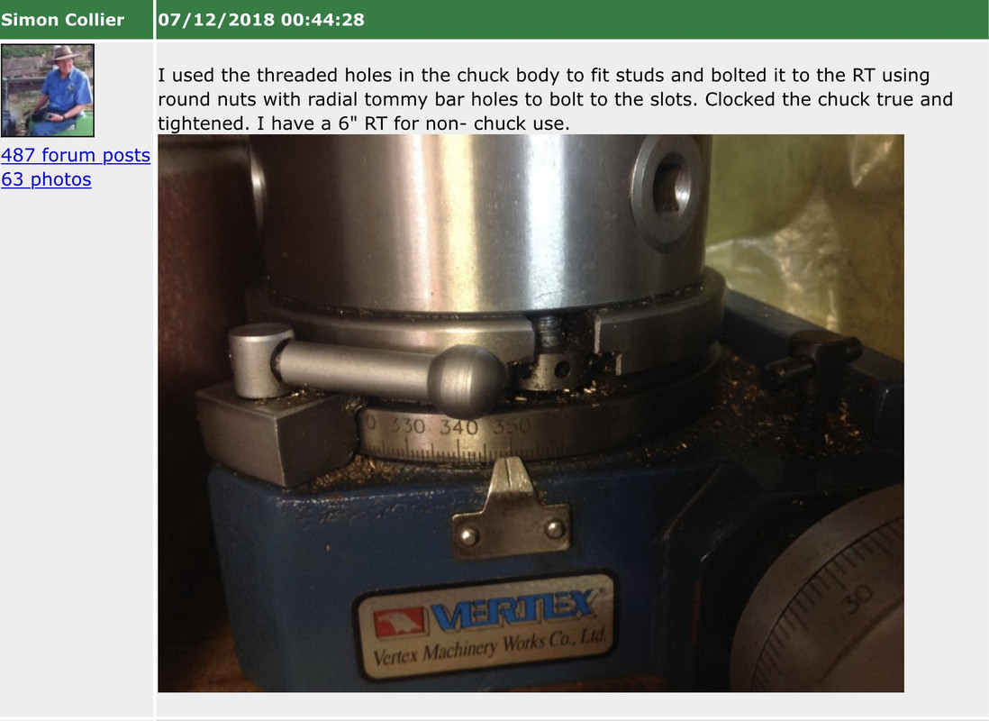
| 3453 forum posts 23 photos | Thanks for the tip Dave, yes that search is so much better! Sorry, another question. Folks have said four slots are better but how do you fit a scroll chuck with three studs to a table with four slots? I’ve seen a simple way of mounting on a three slot table without any adapters etc, just using studs and round nuts with holes for a Tommy bar. I hope Simon doesn’t mind me posting this but it’s such a clever and simple idea. I’ve seen a RT at a good price but it’s got four slots so I’d be keen to know how to mount my Chuck without having to make an adapter. And why are four slots better anyway?
Edited By Vic on 24/12/2022 18:46:50 |
| JasonB | 24/12/2022 19:09:16 |
 25215 forum posts 3105 photos 1 articles | I have two 3 Jaw chucks mounted on backplates that are a bit larger than the chuck body which allows the backplate to be held to the table with tee nuts, a spigot on the backplate to locate in the table's central hole make sfor easier set up.
4 holes also make sit easier if you want to fit a vice to the table
I would go with 72:1 or 90:1 on a rotary table as anything lower like 40:1 is better for dividing that curved cutting.
|
| Ramon Wilson | 24/12/2022 22:22:32 |
1655 forum posts 617 photos | Yep - Jason beat me to it but my set up is the same - chuck to plate, plate to table. Plate has locating spigot to fit table bore, chuck has locating spigot to fit a recess in the plate and the chuck bore. Ditto with the four versus three slots - four allows more versatile clamping of parts when using table alone. Buying a three slot just so the chuck can be mounted is limiting the versatility for something that is not used that often - well not on the R/T in the fashion shown. Both Jason and I have R/T's larger than the chuck body but you can still have a plate interposed even if the diameters are the same. Though I do use a chuck as shown its rare in comparison to sub plate set ups and four slots are definitely more favourable there. As said I made this R/T over forty year ago from a set of castings supplied by MES if I remember right. It has a 90 tooth wheel - four degrees to the rev each degree split into four. It has served me well over those years and is still used when required - just a week or so ago I made the expansion links for the marine engine using an ali sub plate to extend the diameter. It's done a six spoke steel flywheel in it's time - it carries out milling ops well if used sensibly. Most of it's use has been on IC engine crankcase profiling so it's been well used enough to base advice on. Those large tee slots however were cast in originally - anything but smooth so took a fair bit to clean up. I later added the degree ring and the stops - if there is one thing to improve an R/T it is to fit some kind of adjustable stop set up as they take all the worry of, and potential for, over movement to occur, something that's easily done on a R/T
As always - "yer pays yer money" etc Good luck with yours which ever you chose Vic
Best - Tug Edited By Ramon Wilson on 24/12/2022 22:24:45 |
| Vic | 25/12/2022 11:29:04 |
| 3453 forum posts 23 photos | Thanks for the replies, food for thought. At the price point I’m currently looking at, despite any description, it may be interesting to see if one arrives with 3 or 4 slots! Out of funds at present so I’ll have to wait a while. |
| john fletcher 1 | 25/12/2022 11:46:56 |
| 893 forum posts | I have H/V rotary table and followed an article in MEW, making a stepper motor controller using an Arduino, not easy for me, got there with a lot of help from folks on 'here' thank you chaps. How good it is when cutting a gear, NO losing count, or thin tooth, so after the purchase, I suggest you consider making a controller. John |
| Howard Lewis | 27/12/2022 15:18:32 |
| 7227 forum posts 21 photos | If it is any help, I fit a small 3 or 4 jaw Myford fitting chuck to my HV6 by mounting it on a 2MT /Myford arbor. The arbor is clamped into the taper by a M6 capscrew in a top hat bush Obviously, being a screw fit chuck, if using for radius cutting, the direction of table rotation / cutting forces need to taken into account, to prevent the chuck coming loose... So far, with Tailstock support, have had no problems with unwanted movement when cutting gears (Table face vertical, axis horizontal ) Since gear cutting involves a full depth cut with SLOW feed , this seems to have worked, so far! Have used with table face horizontal, to cut slots, and to graduate with workpiece clamped to the table. HTH Howard.. |

.jpg")


Please login to post a reply.
Magazine Locator
Want the latest issue of Model Engineer or Model Engineers' Workshop? Use our magazine locator links to find your nearest stockist!
Sign up to our Newsletter
Sign up to our newsletter and get a free digital issue.
You can unsubscribe at anytime. View our privacy policy at www.mortons.co.uk/privacy
Latest Forum Posts
- *Oct 2023: FORUM MIGRATION TIMELINE*
05/10/2023 07:57:11 - Making ER11 collet chuck
05/10/2023 07:56:24 - What did you do today? 2023
05/10/2023 07:25:01 - Orrery
05/10/2023 06:00:41 - Wera hand-tools
05/10/2023 05:47:07 - New member
05/10/2023 04:40:11 - Problems with external pot on at1 vfd
05/10/2023 00:06:32 - Drain plug
04/10/2023 23:36:17 - digi phase converter for 10 machines.....
04/10/2023 23:13:48 - Winter Storage Of Locomotives
04/10/2023 21:02:11 - More Latest Posts...
- View All Topics
Support Our Partners


Shopping Partners
Subscription Offer

Latest "For Sale" Ads
- Reeves** - Rebuilt Royal Scot by Martin Evans
by John Broughton
£300.00 - BRITANNIA 5" GAUGE James Perrier
by Jon Seabright 1
£2,500.00 - Drill Grinder - for restoration
by Nigel Graham 2
£0.00 - WARCO WM18 MILLING MACHINE
by Alex Chudley
£1,200.00 - MYFORD SUPER 7 LATHE
by Alex Chudley
£2,000.00 - More "For Sale" Ads...
Latest "Wanted" Ads
- D1-3 backplate
by Michael Horley
Price Not Specified - fixed steady for a Colchester bantam mark1 800
by George Jervis
Price Not Specified - lbsc pansy
by JACK SIDEBOTHAM
Price Not Specified - Pratt Burnerd multifit chuck key.
by Tim Riome
Price Not Specified - BANDSAW BLADE WELDER
by HUGH
Price Not Specified - More "Wanted" Ads...
Get In Touch!
Do you want to contact the Model Engineer and Model Engineers' Workshop team?
You can contact us by phone, mail or email about the magazines including becoming a contributor, submitting reader's letters or making queries about articles. You can also get in touch about this website, advertising or other general issues.
Click THIS LINK for full contact details.
For subscription issues please see THIS LINK.
Digital Back Issues


Donate

 Register
 Log-in
Model Engineer Magazine
- Percival Marshall
- M.E. History
- LittleLEC
- M.E. Clock

ME Workshop
- An Adcock
- & Shipley
- Horizontal
- Mill

Subscribe Now
- Great savings
- Delivered to your door

Pre-order your copy!
- Delivered to your doorstep!
- Free UK delivery!
All Forum Topics > Workshop Tools and Tooling > Rotary Table setup